Radio involves the transmission and reception of electromagnetic radiation with wavelengths exceeding those of infrared light. While this definition might seem technical, the reality is that radio technology forms the backbone of nearly all the wireless communication we rely on daily. From Bluetooth and WiFi to cellular networks and even microwave ovens, they all operate on fundamental radio principles. It’s a century-old technology, yet I found myself surprisingly unaware of its intricacies.
This realization spurred me to learn, leading me to connect with the Pakistan Amateur Radio Society (PARS), my national amateur radio society. PARS is affiliated with the International Amateur Radio Union (IARU), which represents amateur radio to the International Telecommunication Union (ITU), the UN body responsible for coordinating global telecommunication operations and services. Importantly, PARS manages several radio repeaters throughout the country, with one conveniently located in Lahore, my city of residence.
Although radio technology has remained fundamentally unchanged since Guglielmo Marconi’s pioneering experiments in 1895, advancements in circuit design and signal processing have dramatically expanded our transmission capabilities in terms of both data capacity and range. Today, a simple setup consisting of a laptop and under $30 worth of equipment empowers anyone to receive a wide spectrum of radio frequencies, and that’s precisely what we’ll be exploring.
In this software-defined radio tutorial, we’ll delve into setting up a software-defined radio device (SDR) and an antenna to eavesdrop on a conversation between two licensed amateur radio operators facilitated by the Lahore repeater. We’ll then utilize the same equipment to capture an image transmitted from the International Space Station, a spacecraft orbiting Earth. This captured image will then be used to secure the ARISS SSTV Award, showcasing the remarkable ease with which one can explore the radio spectrum using affordable equipment and gain recognition for it. It’s important to note that the hardware used in this article only permits the reception of radio transmissions, not their transmission. This limitation is not a drawback since transmitting requires an amateur radio license, a topic for another time.
Caution! Remember that using radio equipment incorrectly can easily lead to illegal activities. This article will consistently highlight potential pitfalls and provide relevant legal references. My experiments were conducted legally in Pakistan, where I reside. While Pakistan’s federal radio laws are already stringent, your local jurisdiction might be even more so. In 2019, a UN expert faced arrested in Tunisia simply for possessing the same SDR model we’ll be using. It’s entirely your responsibility to ensure full compliance with local regulations while conducting radio experiments. This article does not constitute legal advice; please consult a qualified legal professional for clarification.
Specifically for individuals residing in Pakistan, it’s crucial to secure a PARS shortwave listening (SWL) membership before obtaining any radio receiver. Pakistan’s Wireless Telegraphy Act of 1933 prohibits the possession of wireless telegraphy apparatus. However, this restriction doesn’t apply to SWL members who are permitted to own receivers. Feel free to reach out to me if you’re interested in becoming a PARS member; I’d be happy to provide a reference letter.
Setting Up Our Dipole Antenna and SDR Receiver
You might be wondering, “What exactly is a ‘software-defined’ radio?”. A software-defined radio (SDR) essentially emulates a significant portion of its electronic components through software. Prior to SDRs, dedicated circuitry was required to handle signal processing tasks for radio communication. Functions such as signal filtering, frequency mixing), radio wave detection, signal amplification, modulation/demodulation, and others all relied on separate hardware components. However, as computers have become increasingly powerful, we can now efficiently perform these functions in software, leading to the emergence of software-defined radios.
A popular and affordable SDR receiver option is the Digital Video Broadcast (DVB-T) receiver equipped with the Realtek RTL2832U controller and tuner integrated circuit. Initially intended for video reception, these devices are now repurposed for receiving radio signals, commonly referred to as RTL-SDR devices. I’ll be using the RTL-SDR receiver and dipole from RTL-SDR.com, which currently retails for $29.95 and is shipped internationally. This model boasts a temperature-compensated oscillator (TCXO) and a bias tee, features that, while advantageous, fall outside this article’s scope. It also includes an adjustable dipole antenna kit enabling reception of signals ranging from ~70 MHz to ~1030 MHz.
Day 2 of ARISS Int’l F2F: David Honess from ESA kicks off today’s sessions by proposing engaging ways for children to participate in ISS ham radio initiatives. This includes using tools like Raspberry Pi, RTL-SDR, and SSTV mode communications, facilitated through an online connection with our F2F meeting in Montreal. pic.twitter.com/Mp25cljrAH
— ARISS (@ARISS_status) June 27, 2019
It’s worth noting that the RTL-SDR dipole kit used here was also endorsed by representatives of the European Space Agency during the Amateur Radio in Space (ARISS) International Face-to-face Meeting held in June 2019.
Setting up the antenna is straightforward. Begin by screwing the antenna’s long prongs into the center. Then, mount it on a window using the supplied suction cup. Finally, adjust the dipole arms to an exact length of 49.65 cm (1 foot 7.55 inches) each. Now, connect the female end of the longer provided cable to the dipole’s male end. Next, connect the male end of the longer cable to your SDR. The antenna should be mounted vertically in an outside location as high as possible, preferably on a window using the provided suction cup mount. Here’s a visual representation of the setup:

As a final step, connect the remaining end of the long cable to your SDR and plug your SDR into your computer’s USB port. At this stage, you can choose from a variety of SDR applications. Since I’m using MacOS, which has limited options, I’ll be working with CubicSDR.
| |
Upon launching CubicSDR, you’ll be prompted to choose your SDR and configure its settings. Select the Generic RTL2832U OEM option, as demonstrated in the image. Additionally, adjust the sample rate to 2.048MHz
)
Once CubicSDR is up and running, you can immediately start exploring the radio spectrum. A good starting point is browsing through familiar FM radio broadcasts. In the following video, you can see me scanning through local radio stations accessible to me in Lahore.
Our next objective is to tune in to a conversation between two amateur radio operators on the Lahore repeater. However, before we proceed, let’s take a moment to understand what amateur radio entails.
What Is Amateur Radio?
At this point, you might be curious about what constitutes “amateur” radio. Simply put, amateur radio refers to the use of radio frequencies by licensed individuals for non-commercial purposes. These activities can encompass communication, training, experimentation, contests, and more. The legal definition of amateur radio might differ depending on your jurisdiction. It’s essential to note that amateur radio operators are limited to using frequencies specifically designated for the amateur radio service.
“Amateur Service” encompasses a radio communication service dedicated to self-training, intercommunication, and technical investigations conducted by amateurs. These amateurs are individuals duly authorized under the Amateur Radio Services Regulations, 2004, of Pakistan, driven by a genuine interest in radio technology solely for personal growth and without any financial incentives.
With that clarified, let’s delve into the amateur radio frequencies allocated in our region. These frequencies, along with their definitions, are publicly available in the the Pakistan Table of Frequency Allocations, a document published by the Pakistani Frequency Allocation Board. For ease of reference, I maintain a comprehensive a gist of these allocations. However, for the purpose of this article, let’s focus on the very high frequency (VHF) bands, listed below:
| Unit | Frequency range | ITU – Region 3 | Pakistan's allocations |
|---|---|---|---|
| MHz | 144 – 146 | AMATEUR AMATEUR-SATELLITE 5.216 | AMATEUR AMATEUR-SATELLITE |
| MHz | 146 – 148 | AMATEUR FIXED MOBILE 5.217 | AMATEUR FIXED MOBILE |
An important note on legalities: The RTL-SDR, in this setup, is remarkably powerful. Although you only have access to a limited portion of Pakistan’s (or your local) designated amateur radio spectrum (typically spanning from 1,800 KHz to 250 GHz), it’s crucial to remember that other services operate within this spectrum. It’s vital to be aware of the services you are permitted to listen to and, more importantly, those you are prohibited from listening to. In Pakistan, similar to the UK, listening to transmissions not intended for you or the general public is strictly prohibited. Engaging in such activities can result in hefty fines or even imprisonment according to Pakistan’s Telecommunication (Re-organization) Act of 1996 and the Prevention of Electronic Crime Act of 2016. It’s your responsibility to research and understand the local laws. In the US, the legality of listening to specific transmissions varies by jurisdiction.
Listening to Amateur Radio Operators on the Lahore Repeater
You’re likely wondering about the role of a repeater in all of this. In essence, a repeater serves as an intermediary to extend the range of communication between radio devices. Imagine two individuals, Alice and Bob, wanting to communicate via radio, but the distance between them exceeds their radios’ transmission range. Upgrading their radios would be a costly solution. Instead, they could opt for a more economical approach: installing a repeater station strategically located between them. This repeater doesn’t need to be extremely powerful; it only needs to have enough power to reach both Alice and Bob.
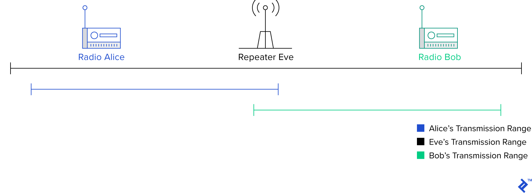
As the name suggests, a repeater receives a signal on one frequency and re-transmits it on another. This simple mechanism effectively expands the coverage area of other radios. Repeaters are usually positioned at elevated locations with minimal obstructions to maximize their reach. Additionally, they often transmit at high power to ensure that even distant radios can clearly receive the signals. The illustration above visually represents how a repeater helps two handheld radios communicate over extended distances, essentially bridging the gap. The Lahore repeater functions similarly, except with amplified power.
The Lahore repeater operates at a frequency of 147.360 MHz*. Before tuning to this frequency, set your modulation selector to narrowband frequency modulation (NBFM/NFM), a concept we’ll delve into later. At this frequency, you’ll notice a distinct pattern of tones recurring every five minutes. For reference, I’ve included a recording of these tones:
Now, what exactly are these tones? A closer examination of the waveform provides some clues.
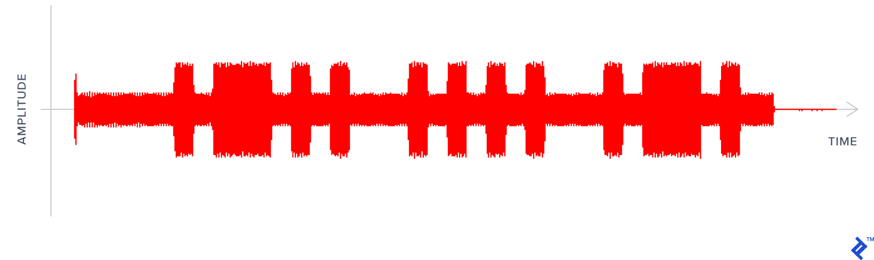
As you might have already guessed, it’s Morse code! Since this waveform represents amplitude over time, the shorter beeps signify dots, while the longer ones represent dashes. Deciphering the audio, we get .-.. … .-., which translates to LHR, the city abbreviation for Lahore. This sequence serves as a confirmation that the repeater is active, you’re tuned to the correct frequency, and you’re indeed listening to the Lahore repeater.
While waiting for further transmissions, I requested my friend Badar Jamal, AP2BDR, a licensed ham operator and the head of the PARS Lahore chapter, to engage in a brief conversation with me while I monitored the Lahore repeater. I had obtained special permission from the Pakistan Telecommunication Authority to operate a radio under the guidance of a licensed operator like AP2BDR. The timing of our conversation coincided with a period of high spectrum congestion, resulting in some background noise. Furthermore, despite my efforts to maintain distance between myself and the RTL-SDR, my transmissions occasionally overpower the device. Nonetheless, you can listen to the recorded conversation below. I was operating under an extension of PARS’ call-sign, AP2ARS/November.
And there you have it—a glimpse into a ham radio exchange between two licensed operators using a repeater. The process remains identical even if they were transmitting directly without a repeater because the RTL-SDR solely receives and doesn’t transmit. However, transmitting equipment requires a more intricate setup due to the need to transmit and receive on different frequencies. If you’re anything like me, this demonstration probably sparked more questions than it answered. Let’s unravel the science behind this in the next section.
Receiving Pictures from a Spaceship: SSTV Events from the International Space Station
The International Space Station (ISS) is a large, man-made satellite orbiting Earth and serves as a space environment research laboratory jointly managed by five space agencies: NASA (United States), Roscosmos (Russia), JAXA (Japan), ESA (Europe), and CSA (Canada). Its ownership and operation are governed by a complex web of agreements and treaties. Technically, the ISS qualifies as both a spaceship, given its nature as a crewed spacecraft, and a satellite due to its Earth orbit.
The ISS hosts an amateur-satellite service under the Amateur Radio on the International Space Station or ARISS program. This program enables you to participate in contact the ISS allowing communication with amateur radio astronauts. ARISS also organizes special slow-scan television (SSTV) events, where it transmits images over 145.8 MHz using narrowband FM. One such event, the ARISS Garriott memorial SSTV activity, took place from August 1st to 4th, 2019. This event aimed to “commemorate the life and achievements of astronaut, scientist, and ham radio pioneer Owen Garriott with a special SSTV event showcasing images from Garriott’s contributions to ham radio during his space missions.” He held the distinction of being the first ham radio operator in space.
For this event, I installed my dipole antenna and RTL-SDR on the roof. The signal, however, was incredibly faint, and I only managed to capture a partial image during a period of exceptionally strong signal using my RTL-SDR. For the rest of the event, I switched to different equipment. It’s worth noting that other PARS members have reported better success with RTL-SDRs coupled with a custom-built antenna constructed using copper tubing and coaxial cable. The process for receiving the signal mirrored the previous example with one key addition: accounting for the Doppler effect.
Noun: Doppler effect
A change in the observed frequency of sound, light, or other waves as the source and observer move towards (or away from) each other. This effect explains the sudden change in pitch we hear when a siren passes by, as well as the redshift observed by astronomers. – Google
The Doppler effect, or Doppler shift, manifests as an apparent change in frequency as the emitter moves closer or farther away. Consider an approaching ambulance siren. As it gets closer, its pitch sounds higher. However, as it passes by, a peculiar phenomenon occurs—the sound abruptly changes, becoming lower in pitch. This puzzled me as a child. Why would ambulance drivers intentionally create this effect? How could they tell they were passing me even when I was indoors? It turns out that this phenomenon applies universally, not just to sound. The Doppler effect affects all waves, including radio and light. Blueshift occurs when celestial bodies appear bluer (indicating a higher wave frequency) as they move towards Earth. Conversely, redshift occurs when they appear redder (indicating a lower frequency) as they move away. For a visual demonstration of this concept, I highly recommend this excellent video.
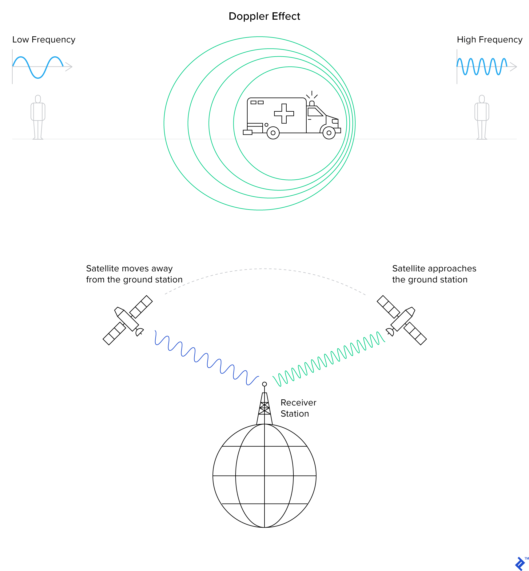
In satellite radio communications, the Doppler shift manifests as an increase in pitch as the satellite approaches and a sudden decrease as it moves away. This shift would appear as follows on the SDR’s waterfall display:
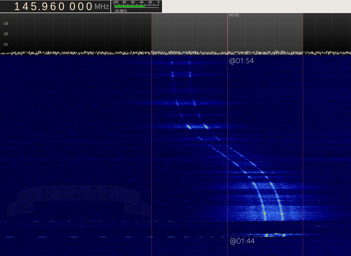
To compensate for this effect, I made slight adjustments to my radio frequency, setting it slightly above 145.8 MHz as the satellite rose, lowering it as it reached its highest point, and further lowering it as it set. Keep in mind that even though I only managed to capture a partial image, this is the audio I received:
If you play this audio using an SSTV decoder like the Robo36 Android application (set to PD120 mode), you should see the following image:
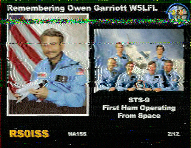
This is a photographic tribute to Owen Garriott, the first ham radio operator to operate from space—a genuine image that I received directly from a spaceship! I used this image to claim the ARISS SSTV Award.

Now, let’s delve into the intricacies of how radio technology operates.
Demystifying Radio: The Science Behind the Magic
If you’re anything like me, you’re eager to understand more. How does someone speaking into a microphone generate invisible waves (what even are waves?) that are then picked up by another seemingly magical box and converted back into sound? Let’s embark on this journey of discovery together. If some concepts seem unclear initially, bear with me. The goal is to shed light on:
- Alternating current and its role in generating magnetic waves
- The electromagnetic spectrum and radio frequencies
- How radio transceivers encode and decode voice data using radio waves
Alternating Current and How It Makes Electromagnetic Waves
You’re probably familiar with direct current (DC), like the current flowing when you connect an LED to a 12V battery. This type of electricity delivers a constant voltage. If we were to graph the current flow in the wire, it would look like this:

As you might know, current passing through a wire generates a consistent magnetic field around it, forming a circular pattern. This can be visualized as:
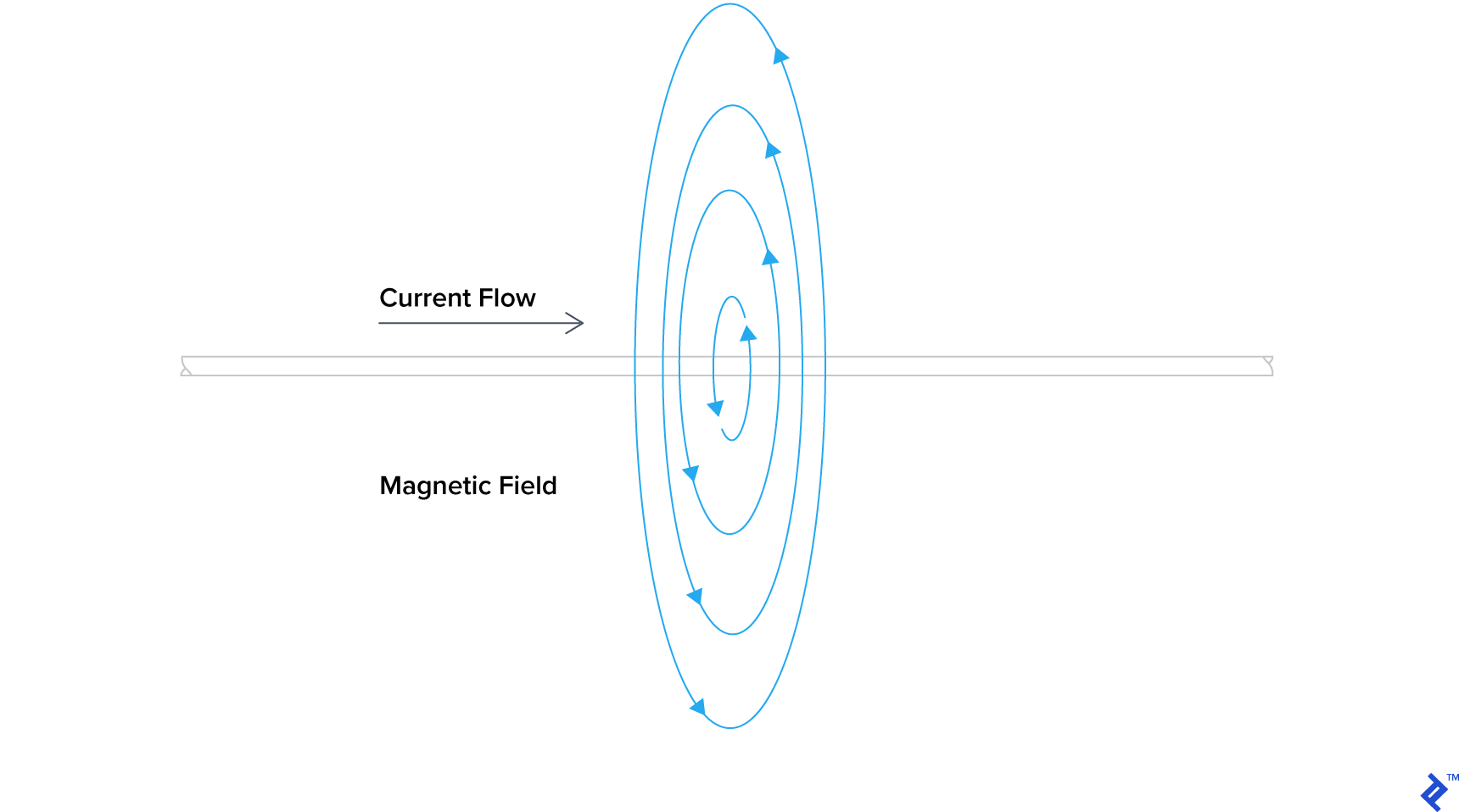
This effect is clearly demonstrated in this YouTube video.
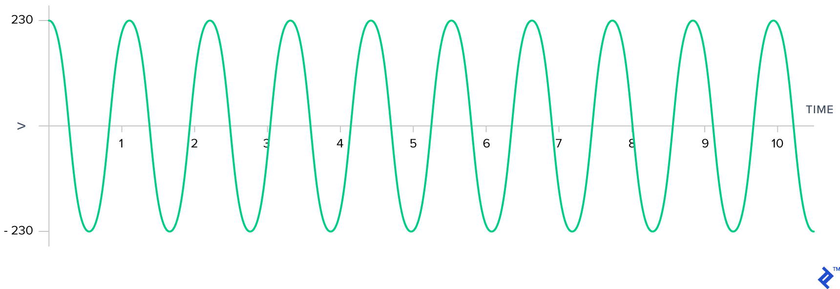
However, DC is not suitable for radio communications. Instead, we rely on its more intriguing and potentially hazardous counterpart: Alternating Current (AC). AC differs from DC in that instead of providing a steady voltage, it alternates the direction of current flow at regular intervals. You encounter AC when you plug devices into a standard wall outlet. In Pakistan, we receive 230 volts alternating at a frequency of 50 Hz (hertz), similar to the UK. In North America, the standard is 120 volts at 60 Hz. For simplicity, let’s assume an AC frequency of 1 Hz. A graphical representation of my mains electricity would resemble this:
Here’s where AC gets interesting: the constantly changing current flow induces a fluctuating magnetic field around the wire. These changing magnetic fields possess a unique property—they can generate currents in nearby wires! This phenomenon is known as electromagnetic induction, forming the basis of all radio technology, which fundamentally relies on electromagnetic radiation and induction using AC waves. Witness this principle in action in this video showcasing a lightbulb being powered by a dipole antenna (cut to the same length as ours) receiving a signal in the 2-meter band:
It’s worth noting that the 2-meter band mentioned here is the same band we used to hear AP2BDR and AP2AUM communicating. But what exactly is this “band” I speak of? We’ll explore this further as we delve into radio frequencies.
Radio Frequencies and The Electromagnetic Spectrum
Electromagnetic (EM) radiation refers to waves composed of electric and magnetic fields propagating through space. In the video above, you observed someone transmitting EM radiation using a dipole antenna and subsequently receiving it using another. This mirrors what we achieved in our experiment, albeit with lower power. While radio waves fall under the umbrella of EM radiation, they are not alone. Other examples include light and ionizing radiation such as X-rays and gamma rays. The key differentiator between these various forms of EM radiation lies in their frequency of oscillation, measured in both frequency (cycles per second) and wavelength (distance between peaks). In the context of amateur radio, frequencies are often categorized into “meter bands.” Let’s delve deeper.

A cycle represents one complete oscillation, typically measured from peak to peak on a graph. Frequency, measured in hertz (Hz), denotes the number of cycles a wave completes in one second. In the diagram above, we observe a frequency of 1 cycle per second or 1 Hz. This implies that the AC wave oscillates, switching between positive and negative voltage, once every second.
To grasp the concept of wavelength, let’s visualize our AC current flowing through a wire. Imagine pausing time and observing an unknown AC current passing through this wire. The peaks represent moments of positive polarization, while the troughs signify negative polarization.

Now, can you determine the length of one cycle in meters by visually inspecting the wire? Remember, a cycle is measured from one peak to the next. Once you have an answer in mind, continue reading.
What you just measured is the wavelength of a signal within a wire. The relationship between a signal’s wavelength and its frequency is defined by the following equation:
$ \lambda = \frac{c}{f} \times VF $
Where:
- $f$ represents the wave’s frequency in Hz
- $c$ denotes the speed of light constant, expressed in meters per second
- $\lambda$ represents the wavelength in meters
- $VF$ represents the velocity factor
The velocity factor ($VF$) is calculated using:
$ VF = v/c $
Where:
- $v$ is the speed at which the signal travels through a specific material
For now, let’s assume that signals propagate through all materials at the speed of light ($c$). This simplification means $v = c$, resulting in $VF = 1$. Consequently, our wavelength equation becomes:
$ \lambda = \frac{c}{f} $
You’ll encounter this simplified equation frequently. However, keep in mind that it holds true only for EM radiation traveling through a vacuum.
When AC current is applied to an ideal antenna, it efficiently radiates EM energy. This process can be visualized as follows:

Notice that the radiated EM radiation oscillates at the same frequency as the AC current driving the antenna. This is why a 450 Hz AC current fed into an antenna will generate a 450 Hz radio signal.
In our earlier demonstration, we listened to AP2BDR and AP2AUM conversing at 147.360 MHz*, where MHz stands for megahertz or 147,360,000 Hz*. The corresponding wavelength for this frequency is 2.03 meters (79.92 inches). This brings us to the concept of meter bands.
Meter bands provide a convenient way to approximate wavelengths. In the realm of amateur radio, mentioning the “2-meter band” implies frequencies with wavelengths around 2 meters.
The electromagnetic spectrum encompasses the entire range of electromagnetic radiation frequencies and their classifications. Broadly, it can be categorized into three main segments: radio waves, light, and ionizing radiation. However, these three categories don’t fully capture the vastness and complexity of the spectrum itself.

According to the ITU, radio waves span from extremely low frequencies (ELF) starting at 3 Hz to extremely high frequencies (EHF) ending at 300 GHz. Beyond 300 GHz, EM radiation transitions into the realm of light. Further along the spectrum, we encounter visible light. As frequencies continue to increase, EM radiation becomes potentially hazardous in the form of ionizing radiation.
How Radio Transceivers Encode and Decode Voice Data From Radio Waves
You might be wondering what a transceiver is. Simply put, a transceiver is a device capable of both transmitting and receiving radio signals. Communication doesn’t necessarily require both parties to possess transceivers; a message can be sent if only one person has a receiver.
Numerous methods exist for encoding and decoding signals. For now, we’ll focus on the two primary techniques, one of which we utilized in our experiment: amplitude modulation (AM) and frequency modulation (FM). If you’ve ever used a car radio, the terms AM and FM are probably familiar. Let’s break down how they work.
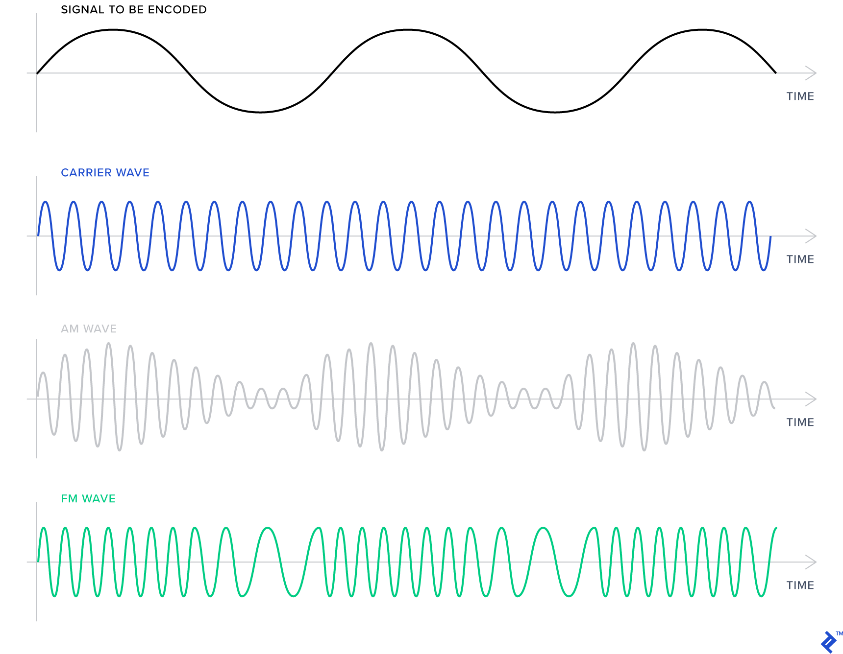
First, let’s introduce two waveforms: a carrier wave and an information signal that we intend to transmit. The carrier wave is a basic wave oscillating at a specific frequency. In our recording, similar to the illustration, our carrier wave was a sinusoidal wave (a smooth up-and-down pattern) with a frequency of 147.360 MHz*. The information signal carries the data we want to transmit. In our case, it was the audio of the conversation between AP2BDR and AP2AUM.
In AM, the information signal is encoded onto the carrier wave by adjusting the carrier wave’s amplitude, making it taller or shorter while maintaining a constant frequency. Conversely, FM involves encoding the information signal by modulating the carrier wave’s frequency. This means that the carrier wave’s height remains constant while its frequency slightly varies.
We used FM for our conversation, which typically produces clearer audio and is less susceptible to noise and distortion compared to AM. This is because distortion primarily affects amplitude. However, FM requires a wider range of frequencies compared to AM. The specific range depends on the filter being used. We opted for narrowband FM (NBFM), while commercial radio stations utilize wideband FM (WBFM). WBFM offers richer sound and greater resilience to distortion but demands a larger frequency bandwidth.
Conclusion
We’ve covered how radios function, explored basic radio regulations, set up a dipole antenna for receiving signals, ventured into the radio spectrum using a software-defined radio, and grasped some fundamental physics behind radio waves, including the core methods of signal encoding and decoding. While radio might seem magical (and personally, I still find it awe-inspiring), it’s a truly remarkable technology. In a future article, we might delve into GNURadio and how to emulate radio functions purely through software.
I hope this has piqued your interest in the fascinating world of radio. Your SDR opens up a realm of possibilities, enabling you to analyze the signals emitted by everyday devices, such as your car’s key fob or a wireless doorbell. Just remember to stay within the boundaries of the law while experimenting. If you decide to pursue becoming a licensed ham radio operator, you’ll have the privilege of transmitting your own signals and engaging in captivating conversations over the airwaves! In Pakistan, transmitting from a radio station operated by a licensed ham is legal, even under their supervision, as long as it’s part of your training. For those interested, I recommend joining PARS or your local amateur radio organization to learn more.
For those seeking comprehensive knowledge about amateur radio, I highly recommend ARRL Handbook for Radio Communications. While its technical depth might seem intimidating initially, with persistent reading, the concepts become clear. It’s an invaluable resource that I frequently consult. For a free (as in freedom and zero cost) alternative to get started immediately, I suggest reading the first five chapters of Wireless Networking in the Developing World. This book delves deeper into the topics discussed here.
*Note: PARS has requested that actual figures not be published online. While the examples provided are technically accurate, the real figures are exclusively accessible to PARS members.