For over twenty years, the inherent intricacy, need for highly skilled engineers, lengthy development cycles, and lack of essential building blocks deterred most developers and architects from tackling big data systems.
However, the recent emergence of new big data technologies has sparked an explosion in big data architectures, capable of processing hundreds of thousands, if not millions, of events per second. Without proper planning, utilizing these technologies could necessitate considerable development work for execution and upkeep. Thankfully, modern solutions make it relatively easy for teams of any scale to leverage these architectural components effectively.
Period | Characterized by | Description |
|---|---|---|
2000-2007 | The prevalence of SQL databases and batch processing | The landscape is composed of MapReduce, FTP, mechanical hard drives, and the Internet Information Server. |
2007-2014 | The rise of social media: Facebook, Twitter, LinkedIn, and YouTube | Photos and videos are being created and shared at an unprecedented rate via increasingly ubiquitous smartphones. The first cloud platforms, NoSQL databases, and processing engines (e.g., Apache Cassandra 2008, Hadoop 2006, MongoDB 2009, Apache Kafka 2011, AWS 2006, and Azure 2010) are released and companies hire engineers en masse to support these technologies on virtualized operating systems, most of which are on-site. |
2014-2020 | Cloud expansion | Smaller companies move to cloud platforms, NoSQL databases, and processing engines, backing an ever wider variety of apps. |
2020-Present | Cloud evolution | Big data architects shift their focus toward high availability, replication, auto-scaling, resharding, load balancing, data encryption, reduced latency, compliance, fault tolerance, and auto-recovery. The use of containers, microservices, and agile processes continues to accelerate. |
Present-day architects face a choice: build their own platforms with open-source tools or opt for vendor-provided solutions. Choosing the open-source route necessitates infrastructure-as-a-service (IaaS), which furnishes the fundamental components for virtual machines and networking, giving engineering teams the flexibility to design their architecture. Conversely, vendors’ pre-built solutions and platform-as-a-service (PaaS) offerings eliminate the need to assemble these basic systems and configure the underlying infrastructure, albeit at a higher cost.
Companies can effectively implement big data systems through a synergy of cloud providers and cloud-native, open-source tools. This approach allows them to construct a robust backend with a fraction of the traditional complexity. Importantly, the industry now boasts acceptable open-source PaaS options that are free from vendor lock-in.
This article presents a big data architecture showcasing ksqlDB and Kubernetes operators, which leverage the open-source Kafka](https://kafka.apache.org/) and [Kubernetes (K8s) technologies, respectively. Additionally, we’ll incorporate YugabyteDB to deliver enhanced scalability and consistency. These systems are powerful individually, but their combined capabilities are even more impressive. We use Pulumi, an infrastructure-as-code (IaC) system, to connect these components and streamline system provisioning.
Outlining the Architectural Needs of Our Sample Project
Let’s establish hypothetical requirements for a system to illustrate a big data architecture designed for a general-purpose application. Imagine we work for a video-streaming company that offers localized and original content. We need to track the viewing progress for each video our customers watch.
Here are our primary use cases:
Stakeholder | Use Case |
|---|---|
Customers | Customer content consumption generates system events. |
Third-party License Holders | Third-party license holders receive royalties based on owned content consumption. |
Integrated Advertisers | Advertisers require impression metric reports based on user actions. |
Let’s assume we have 200,000 daily active users, with a peak load of 100,000 concurrent users. Each user watches two hours of content daily, and we want to track progress at five-second intervals. The data accuracy requirements are not as stringent as those of a payment system, for instance.
This translates to approximately 300 million heartbeat events events daily and 100,000 requests per second (RPS) at peak times:
300,000 users x 1,440 heartbeat events per user over two hours daily (12 heartbeats/minute x 120 minutes/day) = 288,000,000 daily heartbeats ≅ 300,000,000
While simple, reliable systems like RabbitMQ and SQL Server could be considered, our system load surpasses their capacity. A 100% increase in business and transaction volume, for example, would overwhelm these single-server systems. We need horizontally scalable systems for storage and processing. As developers, we must employ robust tools; the alternative could be detrimental.
Before we select specific systems, let’s outline our high-level architecture:
With the system structure defined, we can now begin evaluating suitable systems.
Data Storage: A Cornerstone of Big Data
A database is essential for big data. There’s a noticeable shift away from purely relational schemas toward a hybrid approach combining SQL and NoSQL.
Contrasting SQL and NoSQL Databases
Why do companies gravitate towards one type of database over the other?
SQL | NoSQL |
|---|---|
|
|
Modern databases of both types are increasingly incorporating each other’s strengths. The lines between SQL and NoSQL offerings are blurring, making the selection process for our architecture more challenging. The sheer number of available database industry rankings is staggering, with almost 400 options to choose from.
Distributed SQL Databases: Bridging the Gap
An intriguing development is the rise of a new breed of databases that encompass all the key features of both NoSQL and SQL systems. A hallmark of this emerging class is a single, logical SQL database physically distributed across multiple nodes. While lacking dynamic schemas, this new class boasts:
- Transactions
- Synchronous replication
- Query distribution
- Distributed data storage
- Horizontal write scalability
To avoid cloud lock-in, our design should steer clear of database services like Amazon Aurora or Google Spanner. Our chosen solution must also effectively handle the anticipated data volume. For these reasons, we’ll utilize the high-performing, open-source YugabyteDB for our project needs. The resulting cluster architecture is as follows:

YugabyteDB emerged as the ideal choice because it is:
- PostgreSQL-compatible, seamlessly integrating with a wide array of PostgreSQL database tools such as language drivers, object-relational mapping (ORM) tools, and schema-migration tools.
- Horizontally scalable, allowing performance to scale linearly with the addition of nodes.
- Resilient and consistent at its data layer.
- Deployable across various environments, including public clouds, natively with Kubernetes, or on its own managed services.
- 100% open source, offering robust enterprise features such as distributed backups, encryption of data at rest, in-flight TLS encryption, change data capture, and read replicas.
Furthermore, our chosen product exhibits attributes highly desirable in any open-source project:
- A vibrant and active community
- Comprehensive and well-maintained documentation
- A rich set of tooling
- A dedicated well-funded company providing product support
YugabyteDB aligns perfectly with our architecture. Next, let’s examine our stream-processing engine.
Real-time Stream Processing: Making Sense of the Data Deluge
Recall that our project generates 300 million daily heartbeat events, translating to 100,000 requests per second. This high throughput produces a massive amount of raw data that, in its current form, holds limited value. However, we can aggregate this data to derive meaningful insights: For each user, which video segments did they watch?
Using this aggregated form significantly reduces data storage needs. To transform the raw data, we must implement a real-time stream-processing infrastructure.
Smaller teams lacking big data experience might opt for microservices subscribed to a message broker. These microservices would then retrieve recent events from the database and publish the processed data to another queue. This seemingly straightforward approach brings with it the complexities of managing deduplication, reconnections, ORMs, secrets management, testing, and deployment.
More experienced teams often choose between the costlier AWS Kinesis or the more budget-friendly Apache Spark Structured Streaming. While Apache Spark is open source, it is also vendor-specific. Given our architecture’s emphasis on open-source components and vendor flexibility, we will explore a compelling alternative: Kafka, combined with Confluent’s suite of open-source offerings, including schema registry, Kafka Connect, and ksqlDB.
It’s important to understand that Kafka itself is essentially a distributed log system. While traditional Kafka users rely on Kafka Streams for stream processing, we will leverage ksqlDB, a more advanced tool that encompasses the functionality of Kafka Streams:

More specifically, ksqlDB—a standalone server, not a library—functions as our stream-processing engine. It allows us to write processing queries using an SQL-like syntax. All our functions will execute within a ksqlDB cluster that we typically position near our Kafka cluster to maximize data throughput and processing speed.
The processed data will be stored in an external database. Kafka Connect simplifies this by serving as a framework for connecting Kafka with various data stores, including databases, key-value stores, search indices, and file systems. This eliminates the need to write custom code for importing or exporting topics—Kafka’s term for a “stream”—into a database.
These components work in unison, allowing us to ingest, process (e.g., group heartbeats into window sessions), and store data without having to build traditional services. Our system is designed for scalability and can handle significant workloads due to its distributed nature.
While not without its complexities, Kafka boasts a vast community and extensive documentation, providing support for almost any scenario. Since we aim to minimize infrastructure management, we’ll utilize managed services from Confluent.
Operational Tools: Enhancing Efficiency and Manageability
With the core architectural components in place, let’s explore operational tools that simplify our workflow.
Infrastructure-as-code: Pulumi for Streamlined Deployment
Infrastructure-as-code (IaC) empowers DevOps teams to deploy and manage infrastructure at scale across multiple providers using straightforward instructions. It’s a crucial best practice for any cloud development project.
Teams adopting IaC often gravitate toward Terraform or cloud-specific solutions like AWS CDK. Terraform necessitates learning its domain-specific language, while AWS CDK is limited to the AWS ecosystem. Our preference is a tool that offers greater flexibility in writing deployment specifications and avoids vendor lock-in. Pulumi fits this description perfectly.
Pulumi is a cloud-native platform for deploying any cloud infrastructure, encompassing virtual servers, containers, applications, and serverless functions.
One of Pulumi’s strengths is its support for various popular programming languages, eliminating the need to learn a new one:
- Python
- JavaScript
- TypeScript
- Go
- .NET/C#
- Java
- YAML

Let’s illustrate Pulumi’s functionality with an example. Suppose we want to provision an EKS cluster in AWS. Here’s how we would approach it:
- Install Pulumi.
- Install and configure AWS CLI.
- Pulumi acts as an intelligent abstraction layer over supported providers.
- Some providers require direct interaction with their HTTP API, while others, like AWS, rely on their respective CLI.
- Execute
pulumi up.- The Pulumi engine reads its current state from storage, determines the changes made to our code, and attempts to apply those changes.
Ideally, our entire infrastructure would be managed through IaC. We’d store our infrastructure definition in a version control system like Git, write unit tests, utilize pull requests, and deploy the entire environment with a single click from our continuous integration/continuous deployment (CI/CD) pipeline.
Kubernetes Operators: Automating Complex Deployments
Kubernetes has become the de facto cloud application operating system. Whether self-managed, managed, bare metal, in the cloud, as K3s, or OpenShift, Kubernetes remains at the core. It’s an indispensable component for building robust architectures, except in rare cases involving serverless, legacy, or vendor-specific systems. Its popularity continues to soar.

All our stateful and stateless services will be deployed to Kubernetes. For stateful services like YugabyteDB and Kafka, we will employ an additional subsystem: Kubernetes operators.

A Kubernetes operator is essentially a program that runs within Kubernetes and manages other Kubernetes resources. Consider installing a Kafka cluster with all its associated components, such as the schema registry and Kafka Connect. This would involve overseeing hundreds of resources, including stateful sets, services, PersistentVolumeClaims (PVCs), volumes, ConfigMaps, and secrets. Kubernetes operators alleviate this burden by streamlining the management of these services.
Publishers of stateful systems and enterprise developers are at the forefront of creating these operators. Regular developers and IT teams, in turn, benefit from these operators, which simplify infrastructure management. Operators enable a straightforward, declarative approach to state definition, which is then used to provision, configure, update, and manage the associated systems.
In the early days of big data, developers managed their Kubernetes clusters using raw manifest definitions. The introduction of Helm simplified Kubernetes operations, but further optimization was still possible. Kubernetes operators emerged and, in conjunction with Helm, transformed Kubernetes into a technology that developers could readily adopt.
The widespread adoption of operators is evident in the fact that each system discussed in this article has its own dedicated operators:
Pulumi | Uses an operator to implement GitOps principles and apply changes as soon as they are committed to a git repository. |
Kafka | With all of its components, has two operators:
|
YugabyteDB | Provides an operator for ease of use. |
With all the key components covered, let’s take a high-level look at our system.
Our Architecture: Putting It All Together
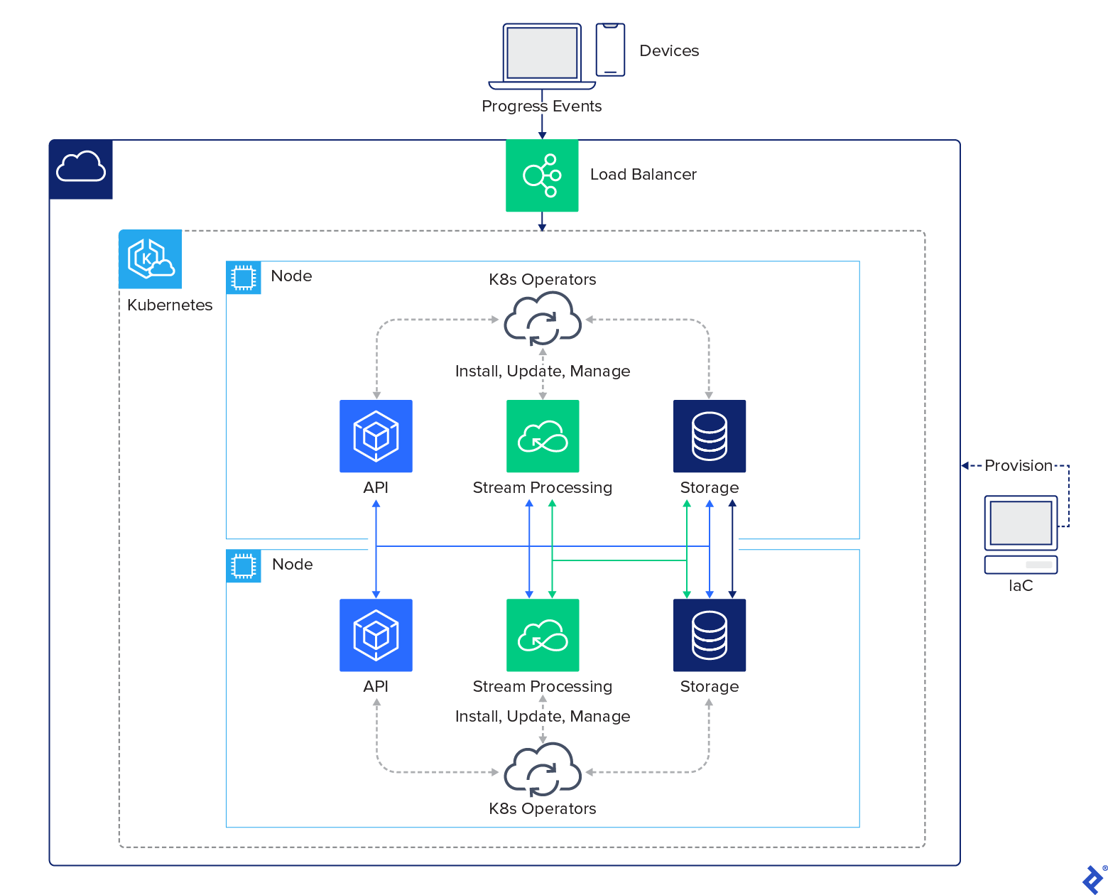
Despite its many components, the overall architecture of our system is remarkably straightforward:

Within our Kubernetes environment, the deployment process is streamlined by Kubernetes operators. By simply installing the Strimzi and YugabyteDB operators, these tools handle the installation of the remaining services. Here’s an overview of our complete ecosystem within Kubernetes:

This deployment exemplifies how modern technologies facilitate the creation of a distributed cloud architecture. Tasks that seemed insurmountable just five years ago can now be accomplished in a matter of hours.
The editorial team of the Toptal Engineering Blog expresses its gratitude to David Prifti and Deepak Agrawal for their invaluable contributions in reviewing the technical content and code samples presented in this article.