Introduction
I recently worked with a university research lab to create vapor sensors that could provide approximate measurements of ethanol vapor levels in an operant chamber. This project was quite engaging.
My lack of experience with Arduino and the limited circuit documentation online led to some challenges. Despite this project being outside my usual area of expertise, I persisted, and the end product turned out well.
This project’s open-source nature stems from the work of Dr. Brian McCool. He developed the Arduino code (available on GitHub), the general project design and suggested parts list, and the concept of using this project in alcohol research.
The Lab
This project was developed for Dr. Anna Radke’s Reward and Addictive Disorders (RAD) Lab at Miami University.
These sensors will be used in an ongoing experiment involving mouse operant chambers. They will provide a visual representation of ethanol vapor pressure within these chambers. This experiment, utilizing these modules, is overseen by Elizabeth Sneddon, who was a PhD candidate at the time and a recipient of the prestigious DSPAN F99/K00 grant from NINDS.
To learn more about Dr. Radke, her team, and their projects, I encourage you to visit the RAD Lab’s website.
Side note: I’d also like to highlight a research paper from the RAD Lab that I co-authored, which can be found on PubMed.
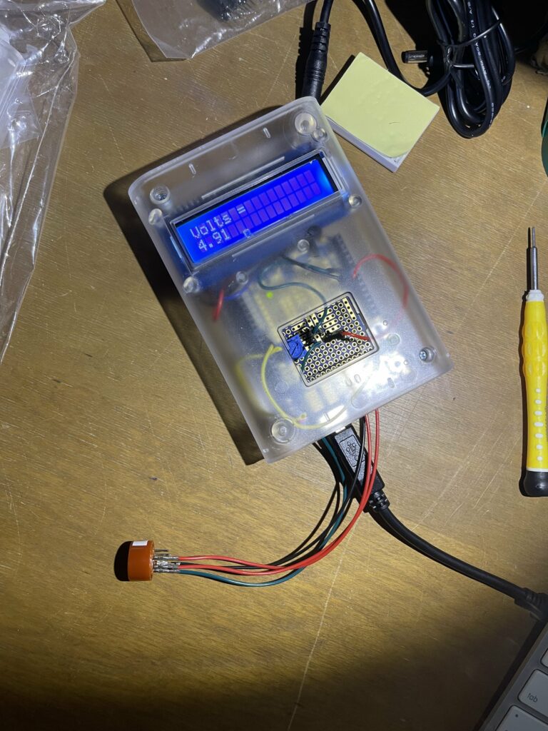
First Successful Unit
The Parts
Per Module Quick List:
- Arduino Uno R3
- Arduino Proto Shield for Arduino Kit (Stackable)
- Clear Enclosure for Arduino (adafruit.com)
- Standard LCD 16x2 screen (options available on adafruit.com and Amazon)
- i2c/SPI character LCD backpack
- MQ-3 alcohol gas sensor (sparkfun.com)
- Power supply (see notes below)
- Standard USB printer cable
- 500Ohm Trim Potentiometer (rat operant boxes); 1k-2kOhm Trim Potentiometer (mouse operant boxes) - a kit containing both is recommended
- Wiring: a kit with various wire types is suggested
- Optional: Breadboard (helpful for testing but not mandatory)
- Optional: Soldering iron kit (required for soldering) and solder sucker kit (recommended for fixing mistakes)
Power supply notes: While a 5V 2A power supply might be considered, I encountered issues with voltage drops. Using a standard USB printer cable with a USB power block (minimum 5V and 2A) is highly recommended. A USB printer cable is also necessary for program transfer to the Arduino.
This list is adapted from Dr. Brian McCool’s recommendations.
Disclosure: As an Amazon Associate, I earn from qualifying purchases. Your support through these links helps maintain this blog, and the pricing remains the same for you. Thank you!
The Circuit
The circuit diagram below, drawn by my father (a radio and broadcast engineer), illustrates the project’s wiring. It can be a valuable resource for anyone building this project. Drawn by RW 09/04/2021
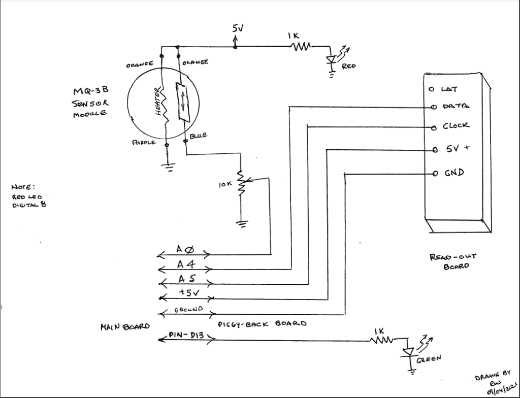
Arduino with MQ-3B Sensor Module Wiring Diagram
Access the diagram here: https://drive.google.com/file/d/1gVgyCg9lm8LaurHVQtRFqXGifgDlCiEb/view?usp=sharing
Assembling the Arduino
The following steps outline the assembly process, though the order can be adjusted as needed.
This was my first Arduino project, so I am by no means an expert. While I found the process enjoyable overall, there were moments of frustration. Unfortunately, I didn’t document the process as thoroughly as I should have. I’ll aim to provide more comprehensive visuals if I have the opportunity to build more units in the future.
Preparing the Protoshield and Connecting to the Mainboard
Assembling the Protoshield requires soldering. The components included with the Protoshield should be arranged as shown in the image below. Pay close attention to the placement of capacitors, resistors, switches/buttons, and LEDs. Soldering should be done from the board’s underside.
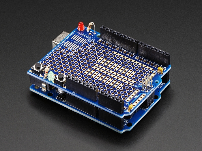
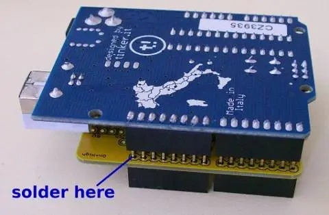
Align and solder the black pinouts as illustrated in the image above, also from the bottom (see image below for clarity). These will be used to connect the Protoshield to the Mainboard by inserting the pins into the corresponding pinouts.
Your assembled Protoshield and Mainboard should resemble the first image.
Connect the LCD Backpack to the LCD Screen
The backpack connects to the screen using the 16-pin connector. Solder all 16 pins to the front of the screen using the short ends of the connectors (see image below).
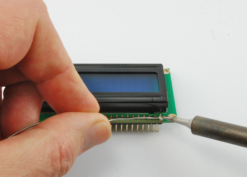
Tip: Attach the 5-screw pins to the backpack before soldering it to the screen. Adding them afterward is considerably difficult.
Flip the assembly over and solder all 16 pins of the backpack as depicted in the image below.
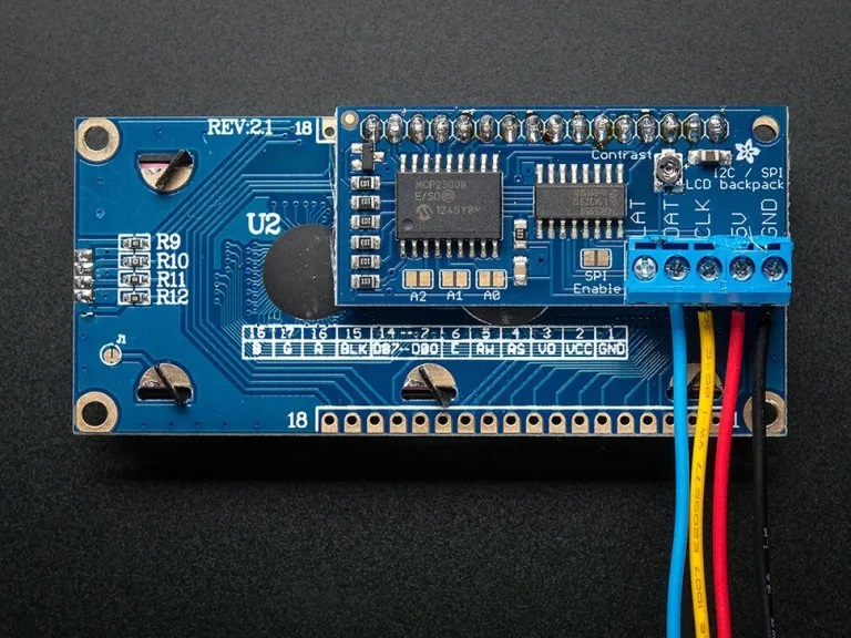
The GND, 5V, CLK, and DAT ports are labeled as the READ-OUT BOARD on the diagram.
Wire the Protoshield
While I don’t have many detailed photos of the wired Protoshield, the image below demonstrates how I connected the 5V and Ground from the Mainboard to their central counterparts on the Protoshield. This allows for easy access when soldering the remaining required 5V and Ground wires.
Using a breadboard during the wiring process is highly recommended. As shown in the image below, a breadboard allows you to test your connections before making them permanent. While some components will require soldering (e.g., screen, backpack), it’s beneficial to test your wiring on the breadboard first.
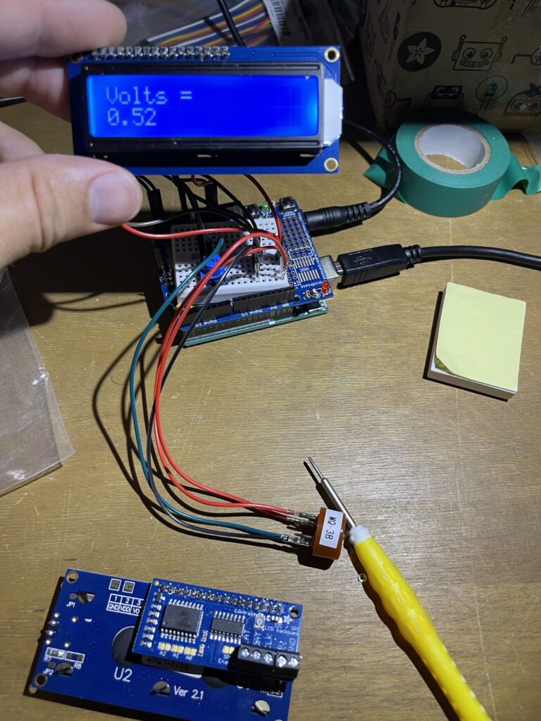
Successful Test Readout with Breadboard
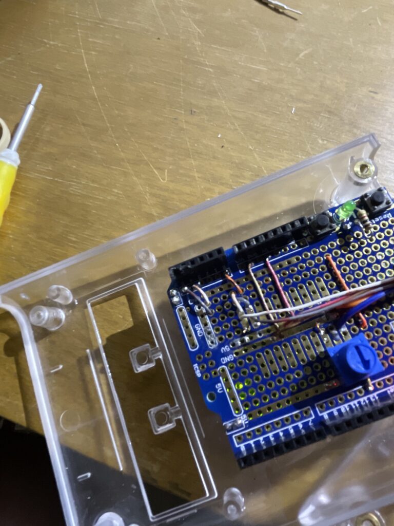
Cleaned Up Wiring
Programming
Download the code provided by Dr. McCool on GitHub. For instructions on uploading the code to your Arduino, refer to this helpful post. Once the connections are made as described and the program is uploaded, your screen should display the voltage reading.
Fine-Tuning the Read-Out
The backpack includes a small, circular “Contrast” potentiometer near the top-right corner. If your screen illuminates but doesn’t show a reading, adjust the contrast using this potentiometer. I found it necessary to fine-tune the contrast for each module I built.
Caution: The potentiometer is fragile and easily damaged, as illustrated in the image below. Exercise caution when adjusting it to avoid breakage. My broken potentiometer required rewiring the module with a new external potentiometer for contrast control. While I don’t currently have a wiring diagram for this situation, I recommend replacing the backpack if you encounter this issue.
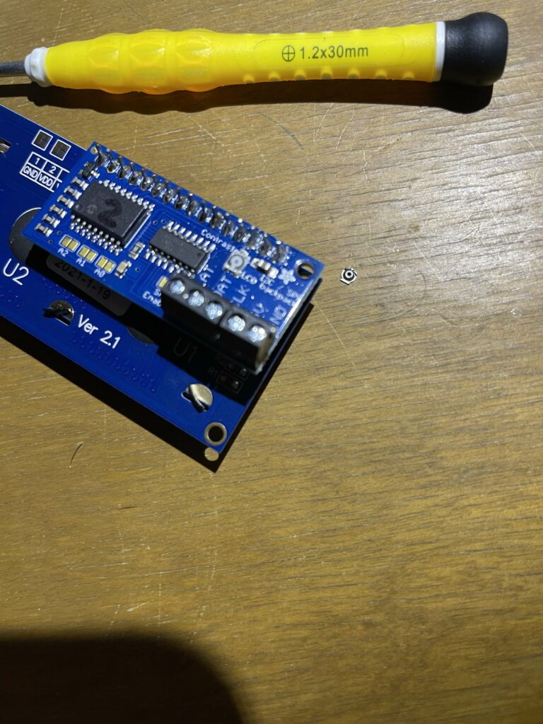
Broken Backpack Potentiometer
Wrapping Up
Congratulations! I hope this tutorial was beneficial in guiding you through the process of building your own sensor module. I trust that this information will be valuable for both your research and personal endeavors.
First Successful Unit
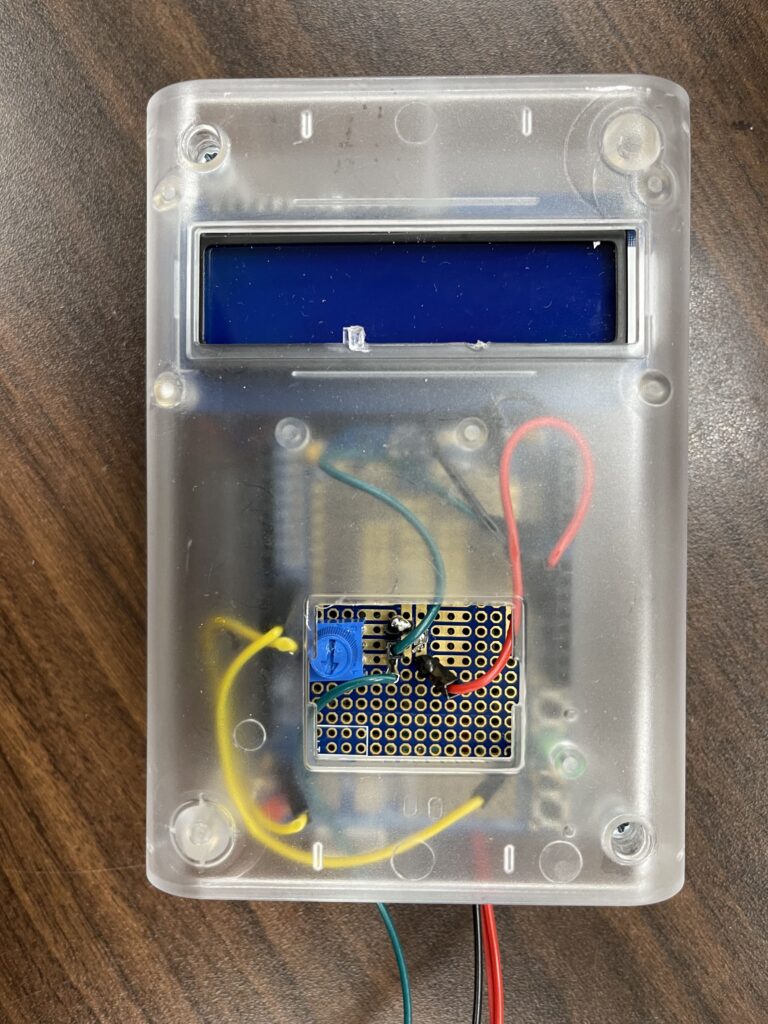
First Completed Unit
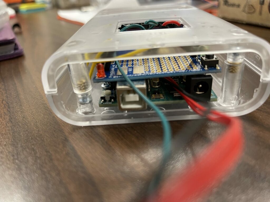
Undershot of a Successful Build