The development of tools like DirectX and OpenGL has significantly simplified the process of creating desktop applications with 3D rendering capabilities. While these technologies have become more accessible over time, driven by the competition between DirectX and OpenGL, which has led to better documentation and resources, there are still some hurdles for new developers entering this field.
DirectX, developed and maintained by Microsoft, is exclusive to the Windows platform. Conversely, OpenGL is a cross-platform 3D graphics API with a specification managed by the Khronos Group.
This introduction to OpenGL demonstrates building a basic application for rendering 3D text models using Qt/Qt Creator for UI implementation, ensuring easy compilation and execution on various platforms. The complete source code for this prototype is available available on GitHub.
This application aims to generate 3D models from text, save them in a simple file format, and enable opening and rendering these models. The rendered 3D model allows rotation and zooming for a better depth perception.
Getting Started
Before diving in, we need to set up our development environment with essential tools. First, download the Qt framework and its utilities from www.qt.io or utilize your operating system’s package manager if available. While some familiarity with the Qt framework is beneficial, it’s not mandatory to follow along as the prototype uses straightforward framework features.
For Windows users, Microsoft Visual Studio 2013 can be utilized. Ensure you have the correct Qt Addin for Visual Studio.
You may choose to clone the repository from GitHub while reading through this tutorial.
OpenGL at a Glance
Let’s start by creating a simple Qt application project with a single document widget. Initially, this bare-bones widget won’t yield much when compiled and run. We’ll use Qt designer to add a “File” menu containing “New…”, “Open…”, “Close”, and “Exit” options. The code connecting these menu items to their actions can be found in the repository.
Clicking “New…” should display a dialog similar to this:
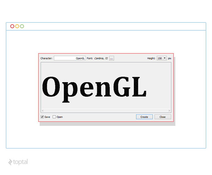
This dialog allows users to input text, select a font, adjust the output model’s height, and generate a 3D model. Clicking “Create” should save the model and optionally open it based on the user’s selection in the lower-left corner. The objective here is to convert the inputted text into a 3D model for rendering.
The project maintains a simple structure with components organized across several C++ and header files:
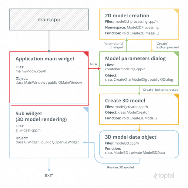
createcharmodeldlg.h/cpp
These files define a QDialog-derived object, implementing the dialog widget for user input, font selection, and model saving/display options.
gl_widget.h/cpp
These files house the QOpenGLWidget-derived object implementation. This widget facilitates 3D scene rendering.
mainwindow.h/cpp
These files contain the implementation of the main application widget and remain mostly unchanged from the Qt Creator wizard’s generated code.
main.cpp
This file holds the main(…) function, responsible for creating and displaying the main application widget.
model2d_processing.h/cpp
These files handle the creation of the 2D scene.
model3d.h/cpp
These files contain structures to store and manipulate 3D model objects (e.g., saving, loading).
model_creator.h/cpp
These files implement the class responsible for creating the 3D scene model object.
Implementing OpenGL
For conciseness, we’ll skip the straightforward UI implementation in Qt Designer and the code defining interactive elements’ behavior. Let’s focus on the interesting aspects of 3D model encoding and rendering.
The initial step in transforming text to a 3D model involves converting the text into a 2D monochrome image. This allows us to identify pixels forming the text and those representing empty space. While simpler methods exist for basic text rendering in OpenGL, this approach provides insights into the finer details of OpenGL 3D rendering.
To generate this image, we create a QImage object with the QImage::Format_Mono flag. A monochrome image suffices as we only need to distinguish between text and background pixels. Upon user input, we dynamically update this QImage object, fitting the text within the user-defined height based on font size and image width.
Next, we iterate through all pixels forming the text, which in this case are the black pixels. Each pixel is treated as a distinct square unit. We then generate a list of triangles, calculate their vertex coordinates, and store this data in our 3D model file.
With our custom 3D model file format ready, let’s move on to rendering. Qt provides the QOpenGLWidget for OpenGL-based 3D rendering. To use this widget, we override three functions:
- initializeGl() - For initialization code.
- paintGl() - Called whenever the widget needs redrawing.
- resizeGl(int w, int h) - Called with the widget’s width and height whenever it’s resized.
We’ll initialize the widget by configuring the appropriate shaders within the initializeGl method.
| |
The first line ensures that only pixels closer to the viewer are displayed, hiding those obscured by other pixels. The second line sets the shading technique to flat shading. The third line ensures that triangles are rendered regardless of their normal direction.
Once initialized, the model is rendered whenever paintGl is called. Before overriding the paintGl method, we need to prepare the buffer:
| |
We create a buffer handle, bind it to a binding point, copy the source data into the buffer, and finally unbind the buffer.
Inside the overridden paintGl method, we use vertex and normal data arrays to draw the triangles for each frame:
| |
Our prototype utilizes Vertex Buffer Objects (VBOs) for performance optimization. VBOs store data directly in video memory, allowing for direct access during rendering. An alternative approach involves supplying the data (vertex coordinates, normals, colors) directly from the rendering code:
| |
While seemingly simpler, this method incurs significant performance overhead due to data transfer through the relatively slow video memory bus. With the paintGl method implemented, let’s shift our focus to shaders:
| |
OpenGL implements shaders using a language called GLSL. Designed for manipulating 3D data before rendering, this language is used to implement two types of shaders: vertex shaders and fragment shaders. Vertex shaders transform coordinates using a transformation matrix to apply rotation, zoom, and color calculation. Fragment shaders assign color to individual fragments. These shader programs need to be compiled and linked with the context. OpenGL provides straightforward mechanisms to bridge the two environments, allowing access and modification of program parameters externally:
| |
Within the vertex shader, we calculate the new vertex position by applying the transformation matrix to the original vertices:
| |
This transformation matrix is computed by combining several individual matrices: screen scale, scene translation, scaling, rotation, and centering. We obtain the final transformation matrix by multiplying these individual matrices. First, the model’s center is translated to the screen’s origin (0, 0, 0). Rotation is determined by user interaction, allowing them to click and drag within the scene. Cursor positions are tracked upon clicking and dragging, forming a triangle with the scene center. This allows for calculating the rotation angle, which in turn updates the rotation matrix. Scaling is controlled via the mouse wheel, modifying the X and Y scaling factors of the OpenGL widget. A translation of 0.5 is applied to keep the model behind the rendering plane. Finally, to preserve aspect ratio, we adjust the model’s expansion along the longer side (compensating for potential differences in physical dimensions between the OpenGL scene and the rendering widget). The final transformation matrix is calculated as follows:
| |
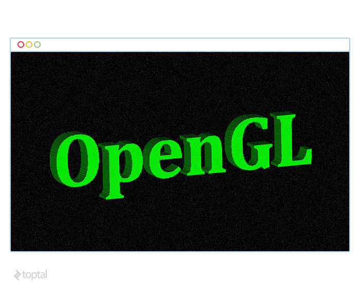
Wrapping Up
This introduction to OpenGL 3D rendering presented a technology that leverages the GPU for rendering, offering efficiency compared to CPU-based rendering. We used a basic shading technique and implemented interactivity through mouse input handling. Data transfer overhead was minimized by avoiding unnecessary communication between video memory and the program. While we rendered a simple 3D text line, the same principles apply to more complex scenes.
This tutorial merely scratched the surface of the expansive world of 3D modeling and rendering. It serves as a starting point for your journey into OpenGL and building 3D applications.