In this piece, we explore Teigha, a library offering a new approach to working with DWG files and ACA elements. We’ll craft a code snippet that constructs a house using ACA elements.
When it comes to programmatically interacting with DWG files and AutoCAD objects, developers are typically limited to ObjectARX or Teigha. Third-party tools designed to read and write DWG files often rely on Teigha as their foundation.
Accelerate Your DWG Production With Teigha Architecture
Teigha Architecture is a collection of libraries enabling the reading, writing, and manipulation of objects from both the original AutoCAD and its derivatives, including ACA. These libraries provide supplementary tools for managing AutoCAD objects, along with rendering engines for visualizing the DWG database.
Here are Teigha’s standout features:
Compatibility with DWG, DXF, BDXF, and DGN file formats.
Rendering of drawing files using GDI, OpenGL, or DirectX, with the ability to select entities.
Programmatic editing and manipulation of CAD data, including:
Exploding an entity into a set of simpler entities.
Applying transformations to entities.
Modifying specific properties of database objects.
Cloning database objects.
Exporting to formats like SVG, PDF, DWF, BMP, STL, and DAE (Collada).
Importing DWF/DAE/DGN files into a .dwg database.
Support for custom objects, allowing developers to create objects usable within any Teigha host application (compatible with .dwg files only).
Internal support for ACIS/Parasolid data, including wireframe and shaded rendering for embedded 3D solids, and access to underlying boundary representation data.
Implementation of custom commands.
Why Teigha Matters for Designers
AutoCAD stores its data in the .dwg file format, a proprietary binary format for two and three-dimensional design data and metadata. DWG is an industry standard, with a vast number of existing drawings requiring support. Beyond AutoCAD itself, Teigha stands out as the sole library capable of loading, saving, and manipulating objects within DWG files.
Here’s why Teigha might be preferred over AutoCAD ObjectARX:
Cost-effectiveness: When building an application that works with .dwg files, developers face a choice: create an AutoCAD plugin or base their application on Teigha. Plugins necessitate an AutoCAD license for all users, a costly requirement. Teigha, however, offers a significantly more affordable pricing model.
Enhanced Flexibility: Teigha empowers developers to create custom CAD applications tailored to specific client needs, free from the constraints of AutoCAD’s core and GUI. Developers gain the freedom to design their own GUIs or leverage existing Teigha-based CAD applications (like BricsCAD or ZWCad) as hosts for their plugins.
Cross-platform Support: Teigha allows for building standalone CAD applications for diverse platforms, including mobile environments like iOS and Android, catering to specialized demands.
Source Code Access: Founding members gain access to Teigha’s source code. This enables customization and the implementation of unique features not present in the standard library.
While Autodesk offers RealDWG, a library allowing C++ and .NET developers to work with AutoCAD® DWG and DXF files, it comes at a higher cost, involves recurring fees, and provides only loading and saving functionality for DWG files. Teigha, in contrast, offers rendering engines and a broader API for comprehensive CAD application development.
Beyond AutoCAD and ObjectARX: An Alternative Approach
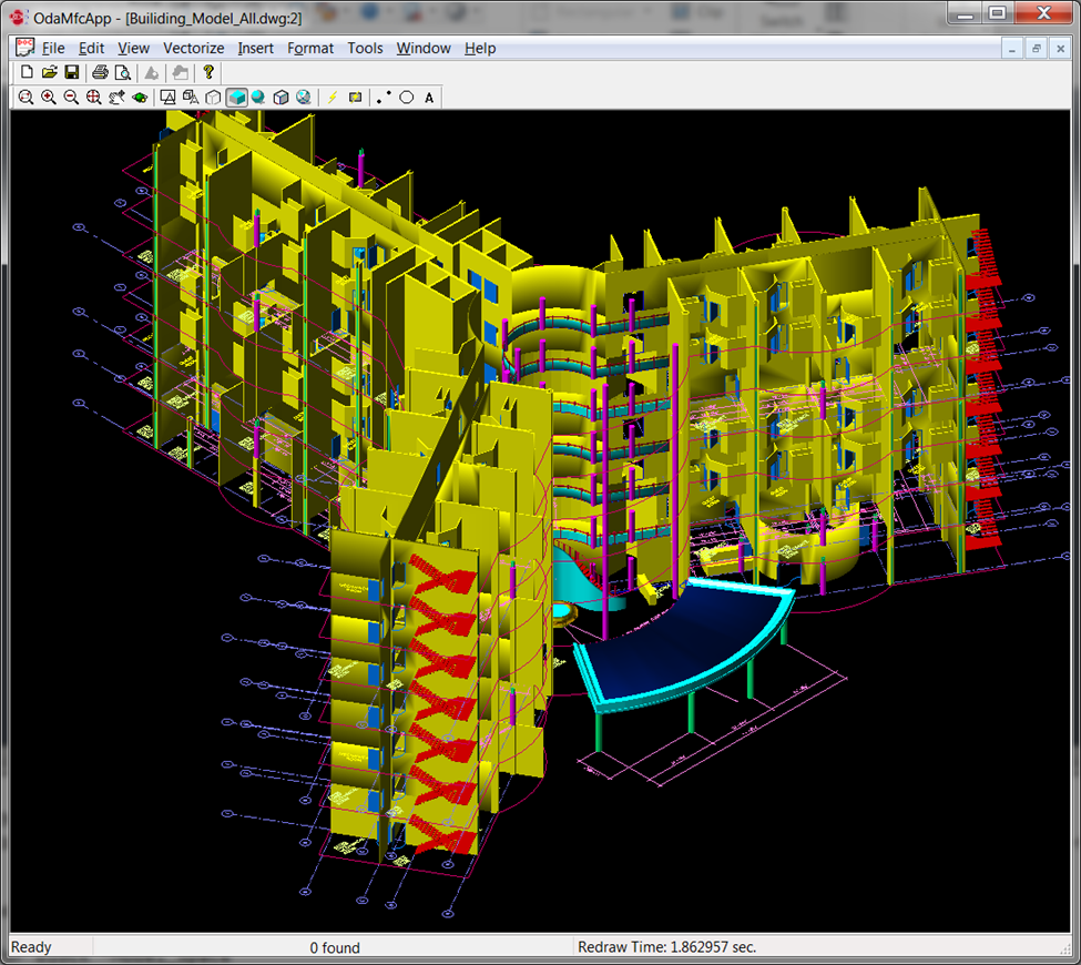
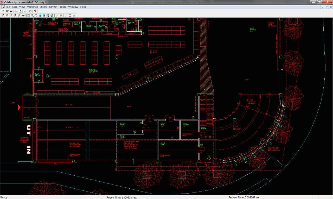
Let’s begin by loading and rendering a DWG drawing using a standard sample from Teigha’s distribution package:
We’ve successfully loaded and rendered the DWG file. (The initial image in this article is a rendering of a different file.) This standard sample is a C++ windowed application, allowing for DWG file loading, viewing, and editing without requiring AutoCAD. Notably, the API for AutoCAD objects closely mirrors that of Teigha objects, simplifying the adaptation of existing ObjectARX plugins for Teigha-based applications.
Numerous AutoCAD alternatives, such as BricsCAD, ZWCad, and IntelliCAD, rely on Teigha for DWG format handling and interaction with ACAD objects.
Understanding AutoCAD Architecture Objects
Let’s delve into architectural objects and their manipulation. AutoCAD Architecture utilizes specialized high-level objects for architectural design, including walls, doors, windows, roofs, etc. These objects are viewport-dependent, meaning their rendering can vary based on camera perspective. Each object is style-driven, inheriting properties from assigned styles. Modifications to a style propagate to all associated objects. Objects are composed of components, each with its own visual attributes like color, line type, material, and scale. For instance, a 3D door might comprise a frame, a door panel, and a glass pane. Rendering can involve different geometries depending on the view mode, leading to variations in component count and settings across different presentations.
Introducing Teigha for Architecture (TA)
For handling architectural objects, developers can either opt for ACA and its open API for plugin creation or leverage Teigha for Architecture, a library developed by Open Design Alliance.
Teigha Architecture is a C++ class library encompassing all fundamental ACA primitives, such as walls, windows, doors, roofs, beams, openings, and more. This library enables loading these objects from any DWG format version and writing (converting) them to the latest DWG version. TA can render any primitives in various views and configurations. Given the interactive nature of ACA objects, TA also supports auxiliary ACA classes and mechanisms, including anchors, display managers, property sets, relation graphs, and more.
Getting Started with the Teigha Architecture API
Having outlined Teigha’s core features, let’s examine a simple command implementation using Teigha. While we’ll use Visual Studio 2005 for this example (despite its age), it’s important to note that Teigha libraries are multi-platform and the distribution package includes solution generators for Visual Studio versions up to 2015. Depending on the license type, developers have access to either the complete source code or pre-built binaries and header files.
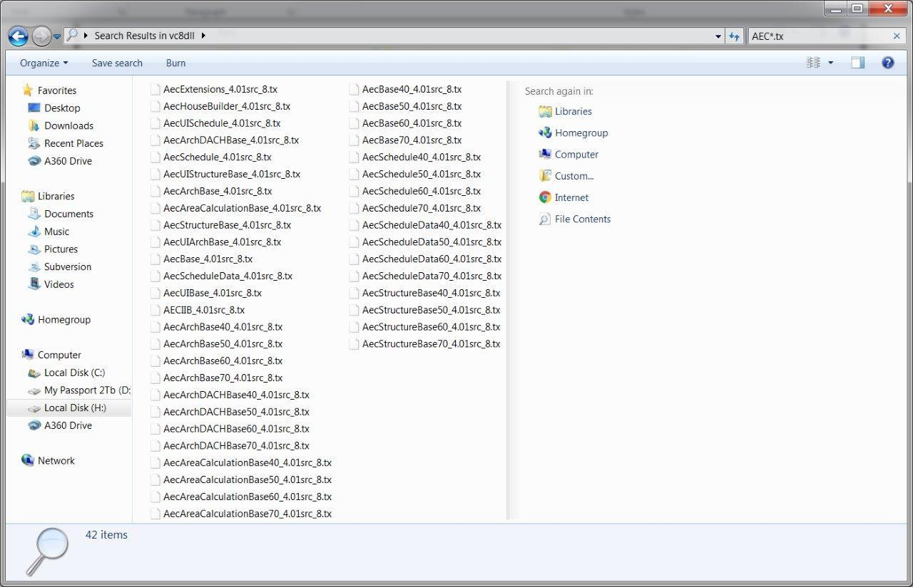
The set of TA libraries appears as follows:
These are essentially standard Windows DLL files (though they can be built for other platforms like iOS, Linux, UNIX, etc.). Corresponding LIB files are located in a separate folder. Along with TA, we’ll need the Teigha Core libraries, as TA functions as an extension built upon Core objects, which implement the primary mechanisms and objects of the original AutoCAD.
Initializing Teigha Architecture
Initializing the library requires a class for platform-specific file operations.
The distribution package provides two pre-built Windows extensions, ExSystemServices and ExHostAppServices, which we can utilize. Next, we initialize the library and the graphics subsystem:
_OdStaticRxObject_ introduces _addRef/Release_ logic to an object. The library stores a reference to the MyServices object for platform-specific operations.
Let’s initialize the TA libraries:
1
2
3
4
5
6
7
8
9
10
11
12
13
14
// Loading of all public Teigha Architecture DRX modules.
// Note that not all calls are necessary for some of them depend on others
// but here we list all of them.
//
// If a program uses TD doesn't modify or create binary files
// it may not load any of DRX modules on start because they will be loaded automatically.
// But if a program modifies or creates binary files then it is highly recommended
// to load all DRX modules program uses.
::odrxDynamicLinker()->loadApp(OD_T("AecBase"));::odrxDynamicLinker()->loadApp(OD_T("AecArchBase"));::odrxDynamicLinker()->loadApp(OD_T("AecArchDACHBase"));::odrxDynamicLinker()->loadApp(OD_T("AecScheduleData"));::odrxDynamicLinker()->loadApp(OD_T("AecSchedule"));::odrxDynamicLinker()->loadApp(OD_T("AecStructureBase"));
AecBase, AecArchBase, etc., are TX modules (DLL libraries) shown in the previous screenshot. While linked using LIB files, they also need initialization as modules. This runtime initialization populates a dictionary of loaded classes in memory. This dictionary facilitates reference casting between TA object types and enables instance creation through a centralized pseudo-constructor mechanism.
For instance, executing the command ::odrxDynamicLinker()->loadApp( OD_T("AecArchBase") ) invokes the AECArchBase::initApp() function within the framework. This function, in turn, registers all library classes in the global dictionary by calling the static rxInit() function for each class:
This registration process enables object creation. We can then create elements like walls using code like _AECDbWallPtr pWall = AECDbWall::CreateAECObject()_. Without this, attempts to create TA class objects would result in exceptions.
Next, we create an empty DWG database:
1
2
OdDbDatabasePtrpDatabase=svcs.createDatabase();
This database serves as a central repository for all created architectural objects. Once populated, it can be saved to a DWG file using:
An AEC dictionary, containing default measurement units for length, area, volume, angle, and print settings, is created within the database. Display representations from the modules are also registered.
With initialization complete, skipping steps can lead to issues like object creation failures, rendering problems (empty screens), or other unexpected behavior.
classMyServices:publicExSystemServices,publicExHostAppServices{protected:ODRX_USING_HEAP_OPERATORS(ExSystemServices);};intwmain(intargc,wchar_t*argv[]){// Initialize TD with system services.
// And create single instance of hostapp services
// for TD database creation.
OdStaticRxObject<MyServices>svcs;odInitialize(&svcs);odgsInitialize();// Loading of all public Teigha Architecture DRX modules.
// Note that not all calls are necessary for some of them depend on others
// but here we list all of them.
//
// If a program uses TD doesn't modify or create binary files
// it may not load any of DRX modules on start because they will be loaded automatically.
// But if a program modifies or creates binary files then it is highly recommended
// to load all DRX modules program uses.
::odrxDynamicLinker()->loadApp(OD_T("AecBase"));::odrxDynamicLinker()->loadApp(OD_T("AecArchBase"));::odrxDynamicLinker()->loadApp(OD_T("AecArchDACHBase"));::odrxDynamicLinker()->loadApp(OD_T("AecScheduleData"));::odrxDynamicLinker()->loadApp(OD_T("AecSchedule"));::odrxDynamicLinker()->loadApp(OD_T("AecStructureBase"));// Create empty TD database.
OdDbDatabasePtrpDatabase=svcs.createDatabase();;// Initialize database with default Teigha Architecture content.
AECArchDACHBaseDatabase(pDatabase).Init();AECScheduleDatabase(pDatabase).Init();AECStructureBaseDatabase(pDatabase).Init();init_display_system(pDatabase);// do something here with TA objects
// Perform "zoom extents" on model space.
{OdDbViewportTablePtrpVT=pDatabase->getViewportTableId().openObject(OdDb::kForRead);OdDbViewportTableRecordPtrpV=pVT->getActiveViewportId().openObject(OdDb::kForWrite);pV->zoomExtents();}OdWrFileBufcBuffer("H:\\TA_test.dwg");pDatabase->writeFile(&cBuffer,OdDb::kDwg,OdDb::kDHL_CURRENT);odgsUninitialize();odUninitialize();return0;}
We’ve added a “zoom extents” command for immediate visualization of added objects when the created file is opened, along with symmetrical library deinitialization. For simplicity, error checking and try/catch blocks around core actions have been omitted.
At this stage, the program generates an empty DWG file viewable in AutoCAD.
Working with Objects
To illustrate working with TA classes, let’s construct a house comprising a floor/foundation, walls, windows, a door, and a roof.
Constructing Walls
We’ll start by adding a single wall. This requires creating a wall style first. Here’s the add_wall_style function:
OdDbObjectIdadd_wall_style(OdDbDatabasePtrpDatabase){OdDbObjectIdidResult=AECDbWallStyle::CreateAECObject(pDatabase,OD_T("Wall Style Created By Teigha(R) Architecture"));AECDbWallStylePtrpWallStyle=idResult.openObject(OdDb::kForWrite);pWallStyle->SetDescription(OD_T("Wall Style Description"));pWallStyle->SetDictRecordDescription(OD_T("Dialog caption"));pWallStyle->SetWallWidth(4);pWallStyle->SetWallWidthUsed(true);pWallStyle->SetBaseHeight(110);pWallStyle->SetBaseHeightUsed(true);pWallStyle->SetJustification(AECDefs::ewjLeft);pWallStyle->SetJustificationUsed(true);pWallStyle->SetAutomaticCleanups(true);pWallStyle->SetAutomaticCleanupsUsed(true);pWallStyle->SetCleanupRadius(4);pWallStyle->SetCleanupRadiusUsed(true);pWallStyle->SetFloorLineOffset(3);pWallStyle->SetFloorLineOffsetUsed(false);pWallStyle->SetRoofLineOffset(-3);pWallStyle->SetRoofLineOffsetUsed(false);AECDisplayManagercDM(pDatabase);AECDbDispPropsWallModelPtrpOverrideModel=AECDbDispPropsWallModel::cast(pWallStyle->OverrideDispProps(cDM.UpdateDisplayRepresentation(AECDbDispRepWallModel::desc())).openObject(OdDb::kForWrite));if(!pOverrideModel.isNull()){pOverrideModel->SetIsDisplayOpeningEndcaps(false);pOverrideModel->GetBoundaryCompByIndex(0)->SetColor(colorAt(4));}AECDbDispPropsWallPtrpOverridePlan=AECDbDispPropsWall::cast(pWallStyle->OverrideDispProps(cDM.UpdateDisplayRepresentation(AECDbDispRepWallPlan::desc())).openObject(OdDb::kForWrite));if(!pOverridePlan.isNull()){pOverridePlan->GetBoundaryCompByIndex(0)->SetColor(colorAt(4));}return(pWallStyle->objectId());}
This function generates an AECDbWallStyle object and configures its parameters. It then utilizes the display manager to adjust colors for plan (2D top view) and model (3D) display representations.
In this case, the wall is set to yellow in the 3D view. While this might seem complex, it reflects the way display representations and the display manager function in ACA. This flexible mechanism offers extensive capabilities at the expense of some initial learning curve.
OdDbObjectId: Runtime References
Database objects reference each other using ObjectId objects, which can be used to obtain object pointers. This mechanism allows for on-demand object loading. Objects don’t need to reside in memory unless actively accessed, enabling partial database loading. ObjectId objects exist for all database entities, but the actual objects are loaded only when needed. This also facilitates memory management by swapping out unused objects.
OdDbHandle should be used for persistent references across program launches.
For instance, the add_wall_style function returned idWallStyle. This style was explicitly created using AECDbWallStyle::CreateAECObject(), and idWallStyle holds the pointer to the object in memory. To modify the style, we need write access:
Smart pointer destructors notify the framework when an object is closed, triggering potential recalculations, notifications, and updates to related objects.
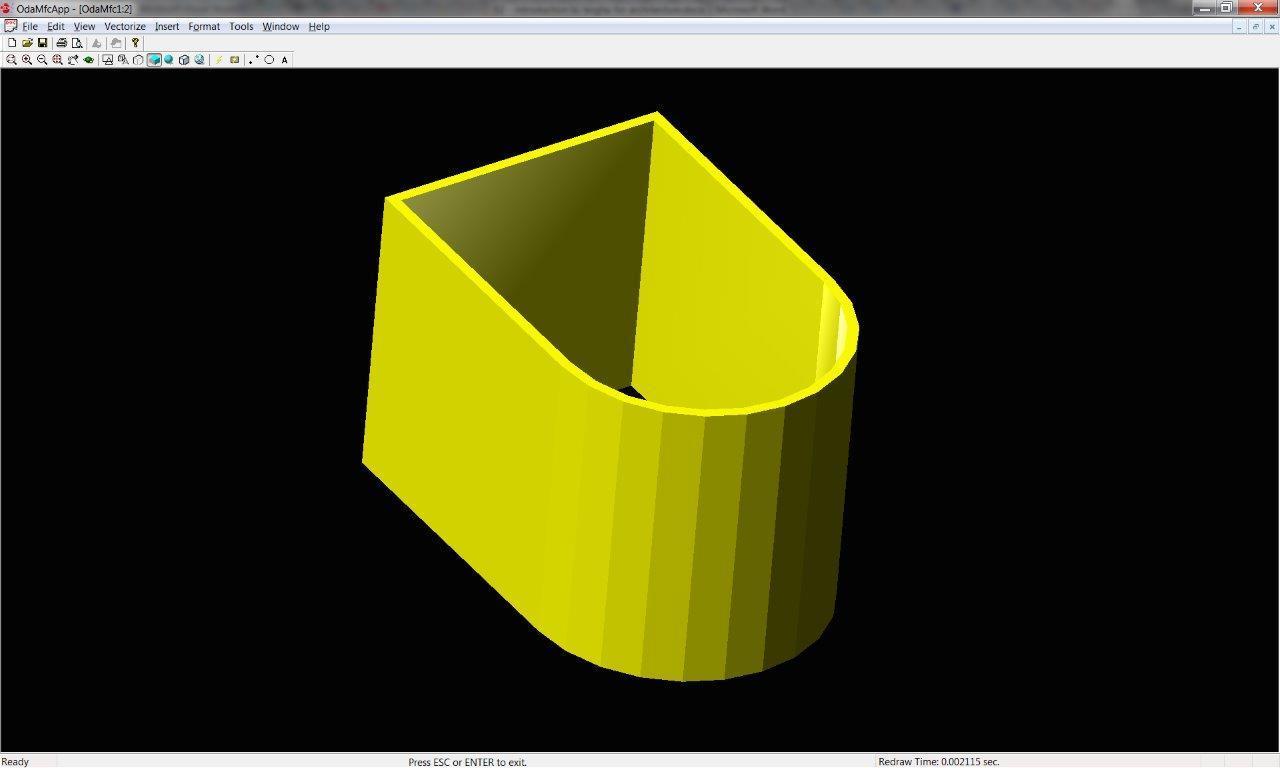
The add_wall function is straightforward, creating an AECDbWall object with the predefined style. This object is added to the database’s model space, a dictionary containing all renderable objects.
The wall’s start point, end point, and curvature are then defined. Walls don’t have to be straight; they can be convex.
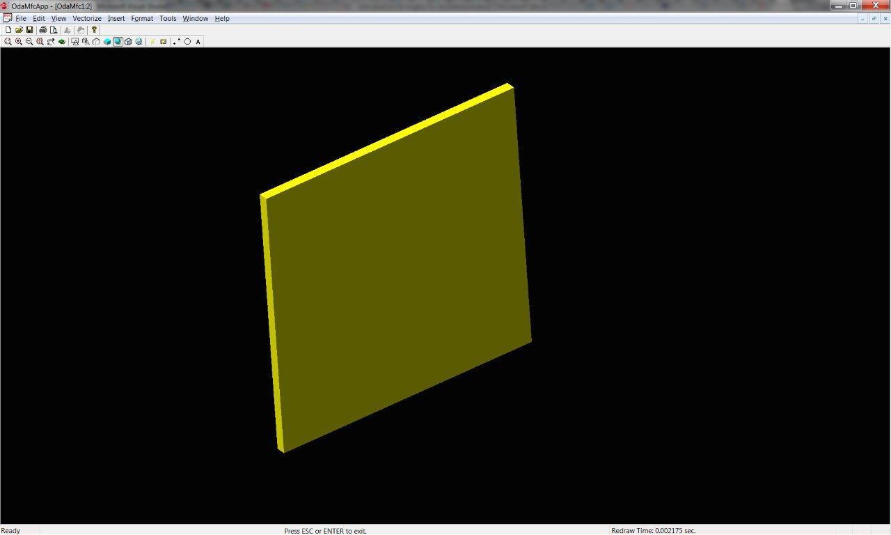
If successful, we obtain a DWG file containing a single yellow rectangular wall. While the provided code sample uses the Teigha distribution package for viewing, the rendering remains consistent in ACA.
The camera has been manually rotated in the 3D view for clarity. The default view is from the top.
OdDbObjectIdidWindowStyle=add_window_style(pDatabase);OdDbObjectIdadd_window_style(OdDbDatabasePtrpDatabase){OdDbObjectIdidWStyle=AECDbWindowStyle::CreateAECObject(pDatabase,OD_T("Window Style Created By Teigha(R) Architecture"));AECDbWindowStylePtrpWindowStyle=idWStyle.openObject(OdDb::kForWrite);pWindowStyle->SetDescription(OD_T("Window Style Description"));pWindowStyle->SetDictRecordDescription(OD_T("Dialog caption"));pWindowStyle->SetAutoAdjustToWidthOfWall(true);pWindowStyle->SetFrameWidth(2);pWindowStyle->SetFrameDepth(5);pWindowStyle->SetSashWidth(2);pWindowStyle->SetSashDepth(3);pWindowStyle->SetGlassThickness(1);pWindowStyle->SetWindowType(AECDefs::ewtGlider);pWindowStyle->SetWindowShape(AECDefs::esRectangular);AECDisplayManagercDM(pDatabase);AECDbDispPropsWindowPtrpOverrideModel=AECDbDispPropsWindow::cast(pWindowStyle->OverrideDispProps(cDM.UpdateDisplayRepresentation(AECDbDispRepWindowModel::desc())).openObject(OdDb::kForWrite));if(!pOverrideModel.isNull()){pOverrideModel->GetFrameComp()->SetColor(colorAt(1));pOverrideModel->GetSashComp()->SetColor(colorAt(2));pOverrideModel->GetGlassComp()->SetColor(colorAt(3));}AECDbDispPropsWindowPtrpOverridePlan=AECDbDispPropsWindow::cast(pWindowStyle->OverrideDispProps(cDM.UpdateDisplayRepresentation(AECDbDispRepWindowPlan::desc())).openObject(OdDb::kForWrite));if(!pOverridePlan.isNull()){pOverridePlan->GetFrameComp()->SetColor(colorAt(1));pOverridePlan->GetSashComp()->SetColor(colorAt(2));pOverridePlan->GetGlassComp()->SetColor(colorAt(3));}return(pWindowStyle->objectId());}
The code demonstrates the creation and database addition of an AECDbWindowStyle object. Style settings are then configured (defaults could be used). Colors for various components are redefined for both 2D and 3D views. These components represent the window’s physical parts: frame, sash, and glass pane.
OdDbObjectIdidWindow01=add_window(pDatabase,idWindowStyle,idWall1,10,10);// Inserts a window into a database using the specified window style.
// If idWall parameter is not null it also attaches the window to the wall.
// Returns Object ID of newly created window.
OdDbObjectIdadd_window(OdDbDatabasePtrpDatabase,constOdDbObjectId&idStyle,constOdDbObjectId&idWall,doubledOffsetAlongX,doubledOffsetAlongZ){AECDbWindowPtrpWindow=AECDbWindow::CreateAECObject(pDatabase->getModelSpaceId(),idStyle);pWindow->SetRise(10);pWindow->SetWidth(40);pWindow->SetHeight(40);pWindow->SetOpenPercent(60);pWindow->SetMeasureTo(AECDefs::eomtOutsideFrame);pWindow->SetLeaf(10);if(!idWall.isNull()){pWindow->AttachWallAnchor(idWall);AECDbAnchorEntToCurvePtrpAnchor=pWindow->GetAnchor().openObject(OdDb::kForWrite);pAnchor->GetXParams()->SetOffset(dOffsetAlongX);pAnchor->GetZParams()->SetOffset(dOffsetAlongZ);}return(pWindow->objectId());}
The add_window() function resembles add_wall() but introduces the anchor object concept.
An AECDbWindow object is created and added to the model space. Settings for this specific window instance are applied. Then, the window is placed within the wall. An AECDbAnchorEntToCurve-derived object handles the attachment.
This anchor object stores X, Y, and Z offsets from the wall’s coordinate system origin to the window’s origin. Calling AttachWallAnchor() creates and adds an instance of this object to the database. While the wall itself remains unaware of any windows, the anchor creation utilizes the relation graph, a mechanism storing object relationships: attachments, inclusions, ownership, etc. Wall modifications notify the relation graph, which in turn updates related objects. This ensures that moving the wall automatically repositions the windows. The relation graph can be accessed to query relationships for specific objects. Windows, however, maintain a reference to their associated anchor, making them aware of their attachment.
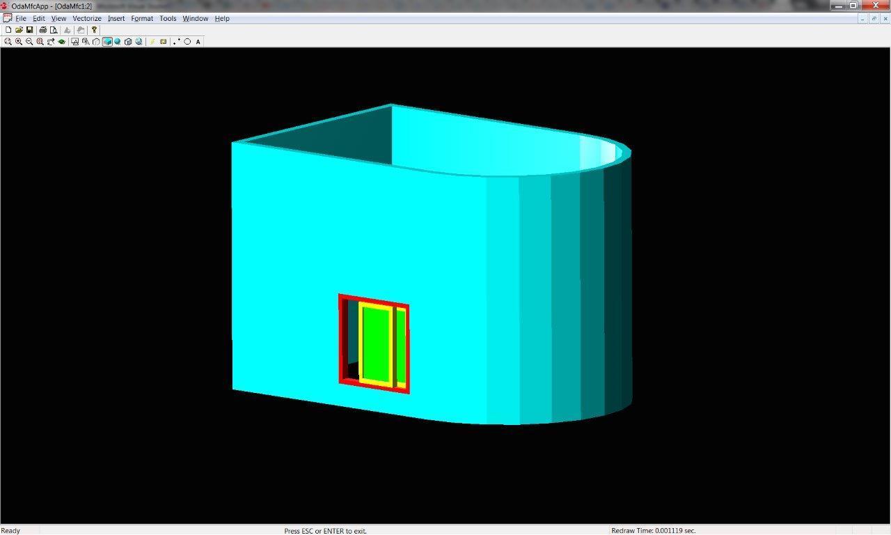
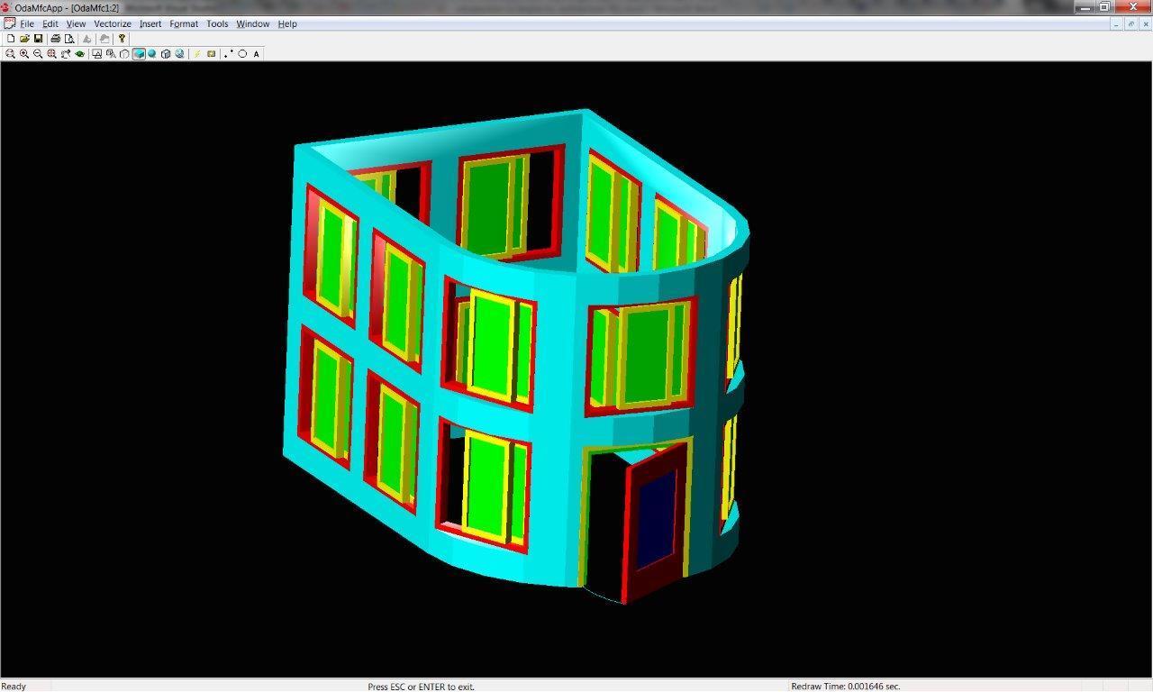
Here’s the result:
Wall colors have been adjusted for better window visibility. (The original code uses blue walls; colors were chosen dynamically for this article.) TA offers numerous predefined window styles and types accessible via enumeration:
Here, AECDefs::ewtGlider and AECDefs::esRectangular are chosen. A wide array of shapes are available, enabling the creation of intricate window designs with multiple sashes and patterned glass. The key takeaway is that this complexity doesn’t necessitate manual piece-by-piece creation or extensive programming. Simple parameter adjustments to existing objects or styles suffice.
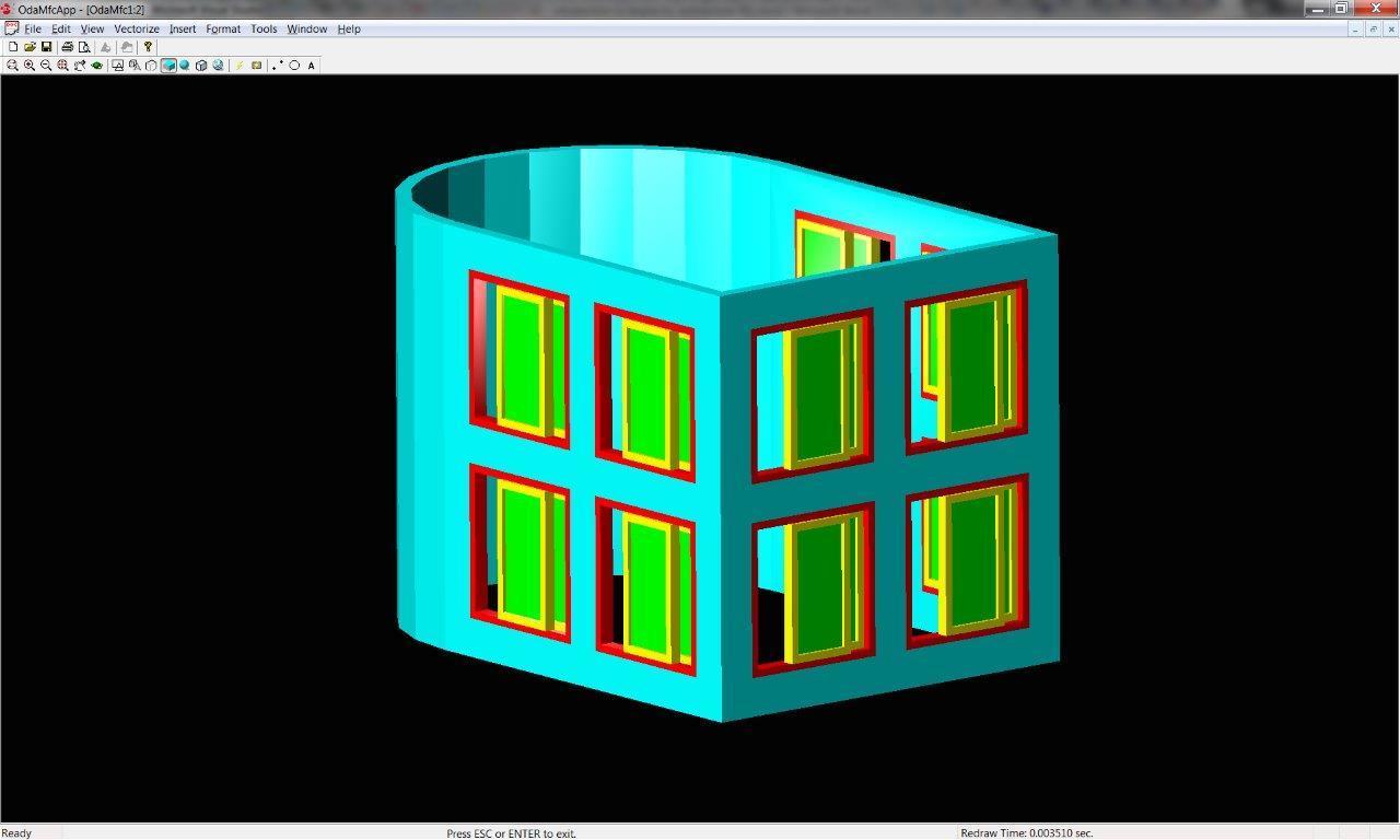
Teigha Architecture objects are inherently complex and highly customizable, providing extensive functionality “out of the box.”
While the code isn’t fully fleshed out, it demonstrates the ability to manipulate individual windows, adjusting their opening percentage, color, etc. Style changes, however, affect all windows using that style.
Adding Doors
To complete the basic structure, let’s add a door. This involves creating a 2D profile for the door panel (leaf with a window), defining a style using this profile, and finally, creating door objects based on this style. Default styles are also an option. Like windows (or any opening), doors are attached to walls using anchors. Here’s the code for add_profile_def, add_door_style, and add_door:
// Inserts profile definition into a database.
// Returns Object ID of newly created profile definition.
OdDbObjectIdadd_profile_def(OdDbDatabasePtrpDatabase){OdDbObjectIdidProfDef=AECDbProfileDef::CreateAECObject(pDatabase,OD_T("Profile Definition Created By Teigha(R) Architecture"));AECDbProfileDefPtrpProfileDefinition=idProfDef.openObject(OdDb::kForWrite);AECGe::Profile2DcProfile;cProfile.resize(2);cProfile[0].appendVertex(OdGePoint2d(0,0));cProfile[0].appendVertex(OdGePoint2d(1,0));cProfile[0].appendVertex(OdGePoint2d(1,1));cProfile[0].appendVertex(OdGePoint2d(0,1));cProfile[0].setClosed();// Forces the contour to be counter-clockwise.
// So if the contour is already ccw this call is not needed.
cProfile[0].makeCCW();cProfile[1].appendVertex(OdGePoint2d(0.2,0.2));cProfile[1].appendVertex(OdGePoint2d(0.2,0.8));cProfile[1].appendVertex(OdGePoint2d(0.8,0.8));cProfile[1].appendVertex(OdGePoint2d(0.8,0.2));cProfile[1].setClosed();cProfile[1].makeCCW(false);pProfileDefinition->GetProfile()->Init(cProfile);return(pProfileDefinition->objectId());}// Inserts a door style into a database.
// Returns Object ID of newly created door style.
OdDbObjectIdadd_door_style(OdDbDatabasePtrpDatabase,constOdDbObjectId&idProfile){OdDbObjectIdidDoorStyle=AECDbDoorStyle::CreateAECObject(pDatabase,OD_T("Door Style Created By Teigha(R) Architecture"));AECDbDoorStylePtrpDoorStyle=idDoorStyle.openObject(OdDb::kForWrite);pDoorStyle->SetDescription(OD_T("Door Style Description"));pDoorStyle->SetDictRecordDescription(OD_T("Dialog caption"));pDoorStyle->SetAutoAdjustToWidthOfWall(true);pDoorStyle->SetFrameWidth(2);pDoorStyle->SetFrameDepth(5);pDoorStyle->SetStopWidth(2);pDoorStyle->SetStopDepth(3);pDoorStyle->SetShapeAndType(AECDefs::esCustom,AECDefs::edtSingle);pDoorStyle->SetProfile(idProfile);pDoorStyle->SetGlassThickness(1);AECDisplayManagercDM(pDatabase);AECDbDispPropsDoorPtrpOverrideModel=AECDbDispPropsDoor::cast(pDoorStyle->OverrideDispProps(cDM.UpdateDisplayRepresentation(AECDbDispRepDoorModel::desc())).openObject(OdDb::kForWrite));if(!pOverrideModel.isNull()){pOverrideModel->GetPanelComp()->SetColor(colorAt(1));pOverrideModel->GetFrameComp()->SetColor(colorAt(2));pOverrideModel->GetStopComp()->SetColor(colorAt(3));pOverrideModel->GetSwingComp()->SetColor(colorAt(4));pOverrideModel->GetGlassComp()->SetColor(colorAt(5));}AECDbDispPropsDoorPtrpOverridePlan=AECDbDispPropsDoor::cast(pDoorStyle->OverrideDispProps(cDM.UpdateDisplayRepresentation(AECDbDispRepDoorPlan::desc())).openObject(OdDb::kForWrite));if(!pOverridePlan.isNull()){pOverridePlan->GetPanelComp()->SetColor(colorAt(1));pOverridePlan->GetFrameComp()->SetColor(colorAt(2));pOverridePlan->GetStopComp()->SetColor(colorAt(3));pOverridePlan->GetSwingComp()->SetColor(colorAt(4));pOverridePlan->GetDirectionComp()->SetColor(colorAt(5));}return(pDoorStyle->objectId());}// Inserts a door into a database using the specified door style.
// If idWall parameter is not null it also attaches the door to the wall.
// Returns Object ID of newly created door.
OdDbObjectIdadd_door(OdDbDatabasePtrpDatabase,constOdDbObjectId&idStyle,constOdDbObjectId&idWall,doubledOffsetAlongX,doubledOffsetAlongZ){AECDbDoorPtrpDoor=AECDbDoor::CreateAECObject(pDatabase->getModelSpaceId(),idStyle);pDoor->SetRise(10);pDoor->SetWidth(40);pDoor->SetHeight(50);pDoor->SetOpenPercent(20);pDoor->SetMeasureTo(AECDefs::eomtOutsideFrame);pDoor->SetLeaf(10);if(!idWall.isNull()){pDoor->AttachWallAnchor(idWall);AECDbAnchorEntToCurvePtrpAnchor=pDoor->GetAnchor().openObject(OdDb::kForWrite);pAnchor->GetXParams()->SetOffset(dOffsetAlongX);pAnchor->GetZParams()->SetOffset(dOffsetAlongZ);}return(pDoor->objectId());}
voidadd_roof(OdDbDatabasePtrpDatabase){AECGe::Profile2DcProfile;cProfile.resize(1);cProfile.front().appendVertex(OdGePoint2d(0,0));cProfile.front().appendVertex(OdGePoint2d(0,110));cProfile.front().appendVertex(OdGePoint2d(110,110));cProfile.front().appendVertex(OdGePoint2d(110,0),-1);cProfile.front().setClosed();cProfile.front().makeCCW();AECDbRoofPtrpRoof=AECDbRoof::CreateAECObject(pDatabase->getModelSpaceId());// Initialize roof profile.
// By default all edges of Roof Profile have single slope of 45 degrees.
pRoof->GetProfile()->Init(cProfile);pRoof->SetThickness(2);//// Manually modify Roof Segments.
AECGeRingSubPtrpRoofLoop=pRoof->GetProfile()->GetRingByIndex(0);if(!pRoofLoop.isNull()){OdUInt32i,iSize=pRoofLoop->GetSegmentCount();for(i=0;i<iSize;i++){AECGeRoofSegmentSubPtrpSeg=pRoofLoop->GetSegments()->GetAt(i);pSeg->SetFaceCount(1);pSeg->SetFaceHeightByIndex(0,110);pSeg->SetBaseHeight(0);pSeg->SetOverhang(10.0);pSeg->SetFaceSlopeByIndex(0,OdaPI4);pSeg->SetSegmentCount(10);}}pRoof->setColorIndex(3);}
The roof is generated from a 2D profile with a counterclockwise traversal direction. makeCCW() ensures this direction, as the algorithm relies on it.
The profile aligns with the walls’ centerline. We then define the slope angle for each profile segment, the number of roof faces, the elevation (Z coordinate) of each face’s top point (SetFaceHeightByIndex), and the overhang. SetSegmentCount() affects only curved segments, controlling the approximation accuracy (number of line segments used to represent the arc).
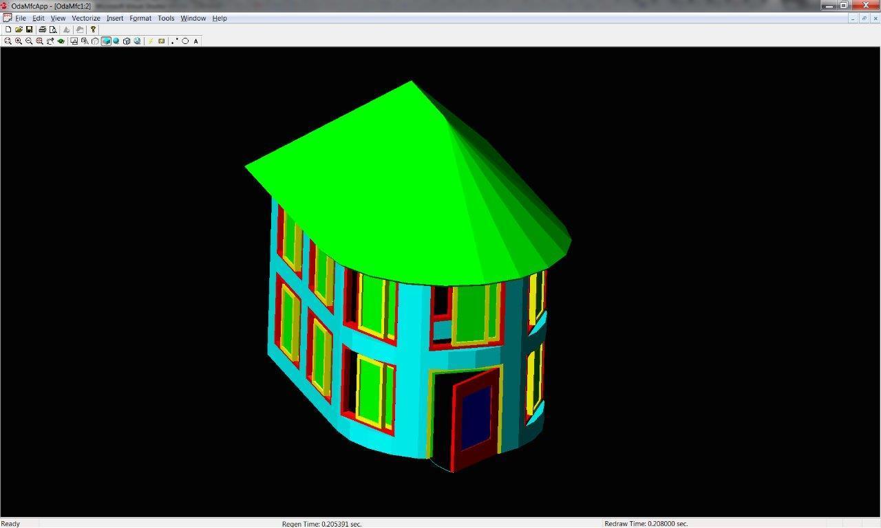
Here’s the completed roof:
The extensive roof settings allow for creating various roof types: gable, hip, hip-and-valley, and more. Each face is a separate editable RoofSlab object.
Adding the Floor
Finally, let’s add a basic floor/foundation using the slab object and the add_slab function:
We define a new floor style and add components to it. Each component represents a floor piece with attributes like thickness, elevation, name, material, index, etc. A floor can have multiple components with varying settings. For instance, different elevations allow a single floor object to represent all floors and ceilings in a multi-story building.
Style settings are applied to a specific object defining the floor’s shape. In this case, a slab is created with a profile matching the walls’ base contour, incorporating a slight offset at the edges. The display manager is used to customize the colors of different floor components.
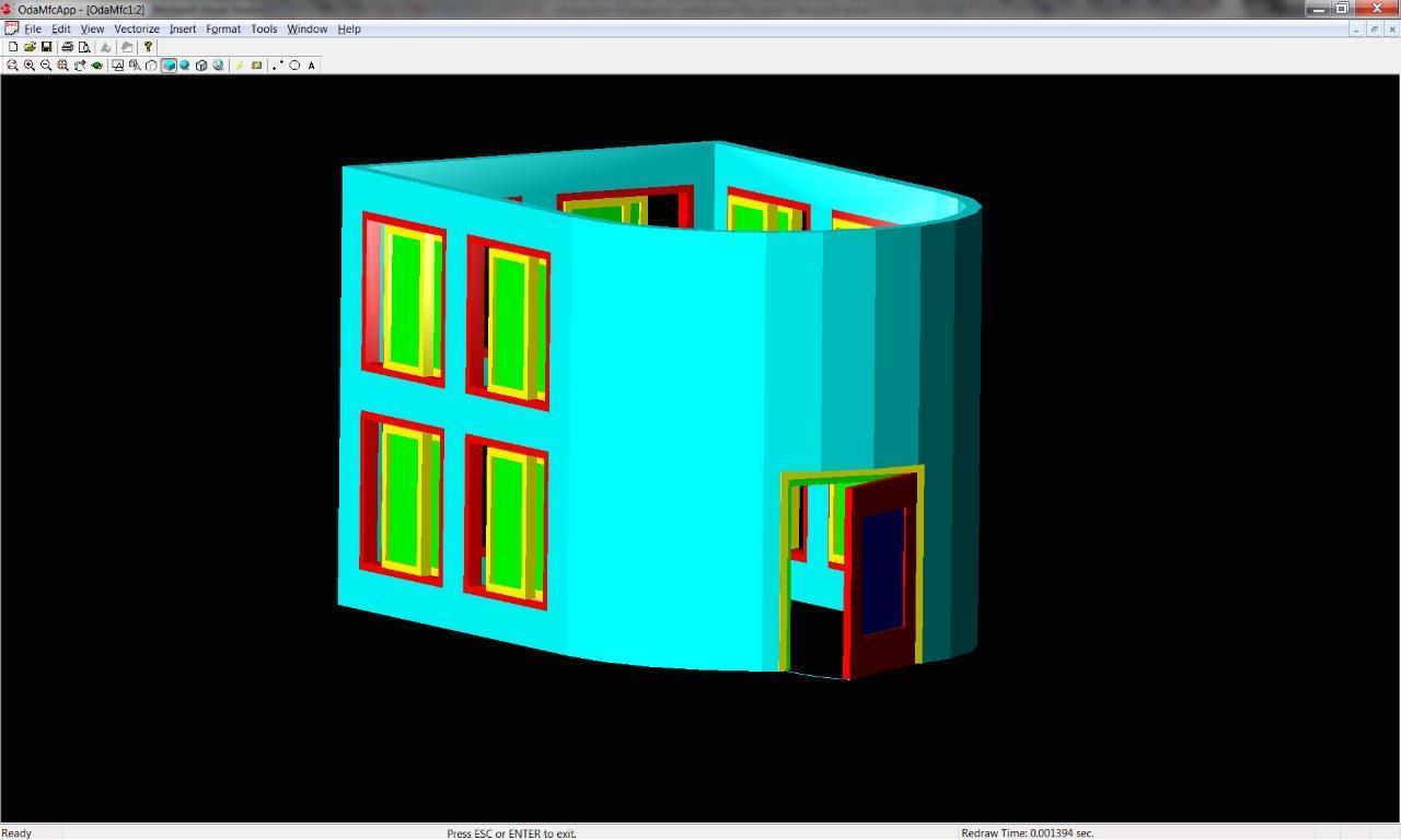
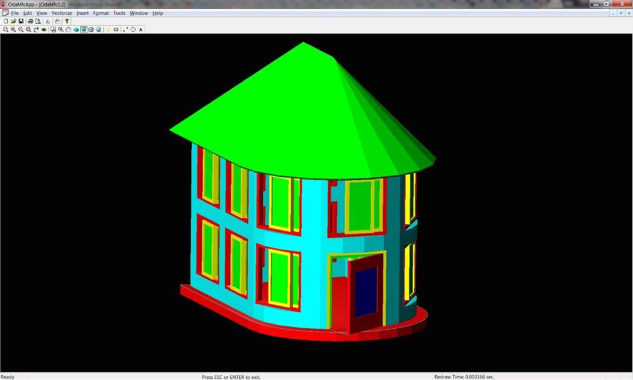
Our completed house:
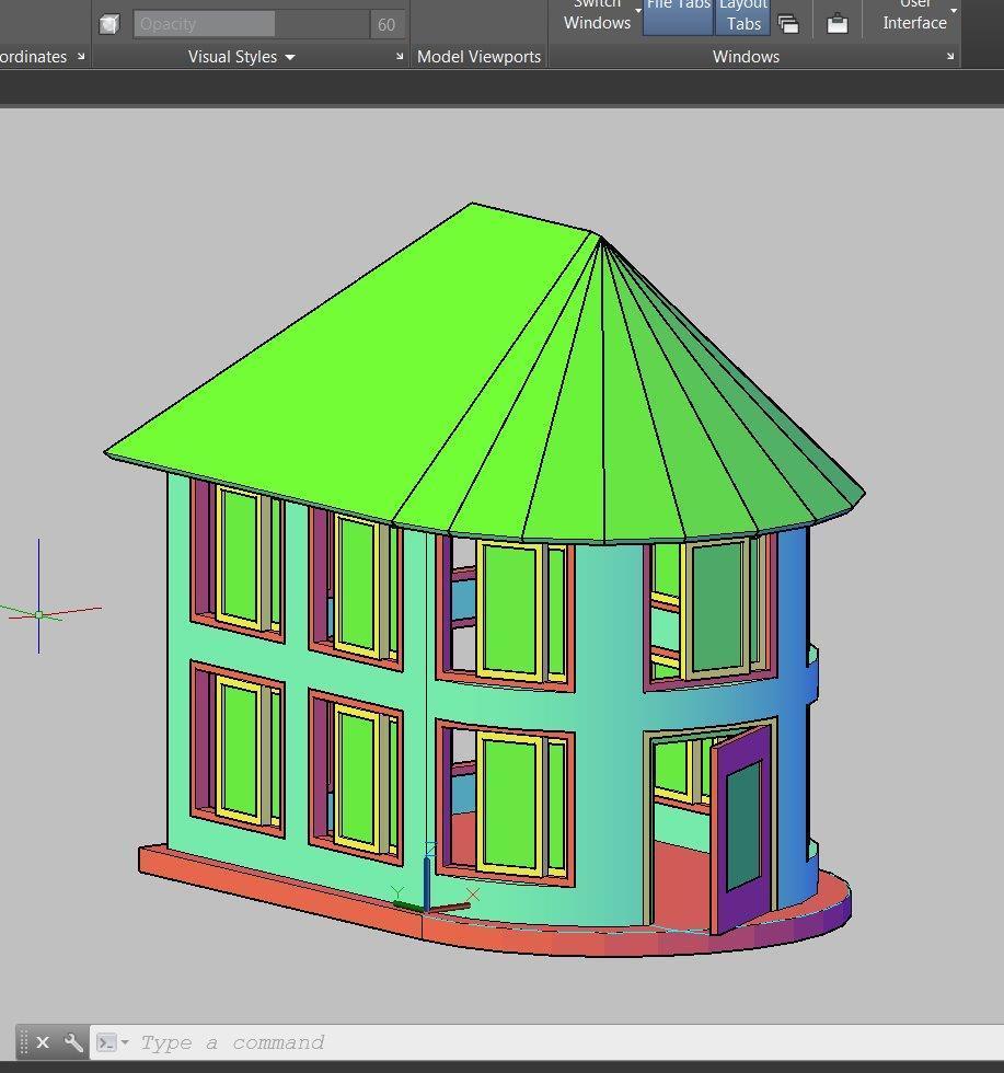
Let’s load the generated DWG file in Autodesk ACA for verification:
The house, now loaded in AutoCAD Architecture, showcasing a more refined rendering.
Conclusion
Leveraging Teigha, we’ve created an empty database, configured it for architectural objects, generated various object types, and successfully saved them to a DWG file in the latest format.
While certain aspects have been simplified for clarity, this exploration highlights the capabilities of Teigha Architecture and positions Teigha as a viable alternative for handling DWG files and interacting with AutoCAD objects.