In August 2007, I was struck by the inefficiency of my standard PC keyboard. Constantly shifting my hands between key blocks, hundreds or even thousands of times daily, was uncomfortable and frustrating. There had to be a better solution.
This realization ignited a wave of excitement as I envisioned designing the ultimate developer keyboard. However, as a freelance embedded software developer, I quickly realized my hardware knowledge was practically nonexistent.
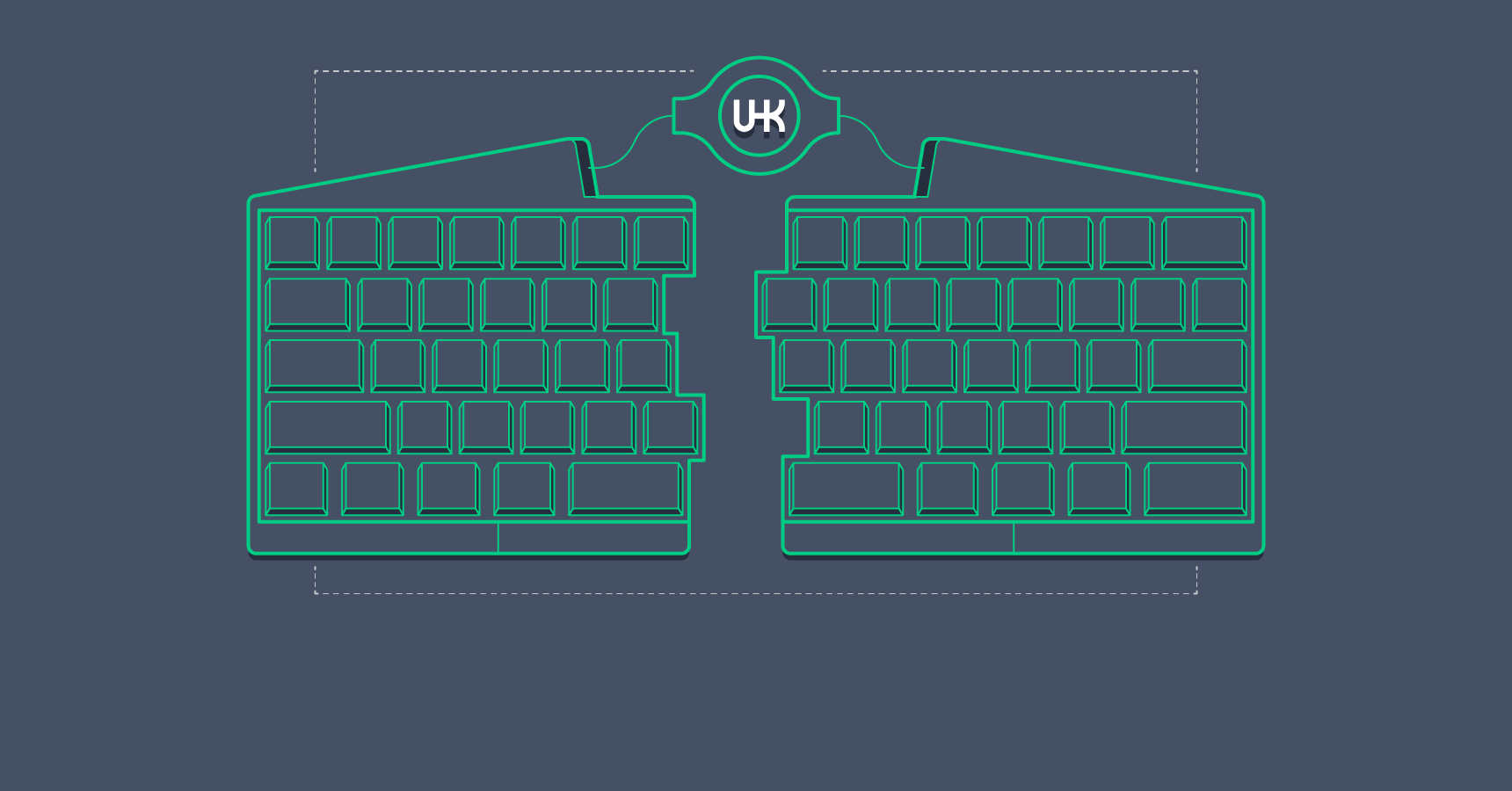
Despite my busy schedule, the thought of building this “hacker keyboard” consumed me. Soon, I dedicated all my free time to the project. I immersed myself in learning new skills, persuaded my incredibly talented mechanical engineer friend András Völgyi to join me, assembled a core team, and devoted countless hours to developing functional prototypes. Today, the Ultimate Hacking Keyboard is no longer just an idea; it’s a tangible reality. We are making steady progress every day, and the launch of our crowdfunding campaign is on the horizon.
Transitioning from a software background with zero electronics expertise to designing and constructing a powerful, marketable hardware device has been an amazing and eye-opening experience. In this article, I’ll delve into the design and functionality of this electronic marvel. A basic grasp of electronic circuit diagrams will be beneficial in understanding the content.
Constructing a Keyboard from Scratch
Having invested thousands of hours into this endeavor, providing a concise answer is challenging. However, let’s approach it progressively. Starting with a simple Arduino board, we can gradually build it up to the Ultimate Hacking Keyboard, creating an engaging and educational experience. Let the keyboard tutorial adventure begin!
Phase One: A Keyless Keyboard
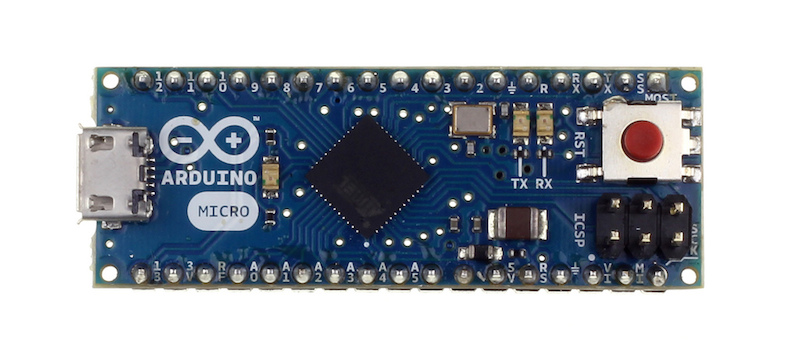
Our first objective is to create a USB keyboard that outputs the ‘x’ character every second. The Arduino Micro](http://arduino.cc/en/Main/arduinoBoardMicro) development board, equipped with the ATmega32U4 [microcontroller - an AVR microcrontroller and the same processor powering the UHK, is perfect for this task.
When working with USB-enabled AVR microcontrollers, the Lightweight USB Framework for AVRs (LUFA) is the go-to library. It transforms these processors into the brains behind printers, MIDI devices, keyboards, and countless other USB devices.
Upon connection to a USB port, a device must transmit specific data structures called USB descriptors. These descriptors, organized in a tree structure, inform the host computer about the type and characteristics of the connected device. Adding another layer of complexity, a device can support multiple functions. Let’s examine the descriptor structure of the UHK:
- Device descriptor
- Configuration descriptor
- Interface descriptor 0: GenericHID
- Endpoint descriptor
- Interface descriptor 1: Keyboard
- Endpoint descriptor
- Interface descriptor 2: Mouse
- Endpoint descriptor
- Interface descriptor 0: GenericHID
- Configuration descriptor
While most standard keyboards only utilize a single keyboard interface descriptor, the UHK, being a customizable programming keyboard, also incorporates a mouse interface descriptor. This enables users to program keys to control the mouse pointer, essentially transforming the keyboard into a mouse. The GenericHID interface serves as a communication channel for exchanging configuration data for all the keyboard’s unique features. You can find the complete implementation of the UHK’s device and configuration descriptors in LUFA here.
With the descriptors established, we can move on to sending the ‘x’ character every second.
| |
USB operates as a polled protocol, meaning the host computer periodically queries the device (typically 125 times per second) for new data to transmit. The CALLBACK_HID_Device_CreateHIDReport() function handles this, sending the ‘x’ character’s scancode to the host whenever the isSecondElapsed variable is set to 1. The main loop sets isSecondElapsed to 1 every second, and the callback resets it to 0.
Phase Two: A Four-Key Keyboard
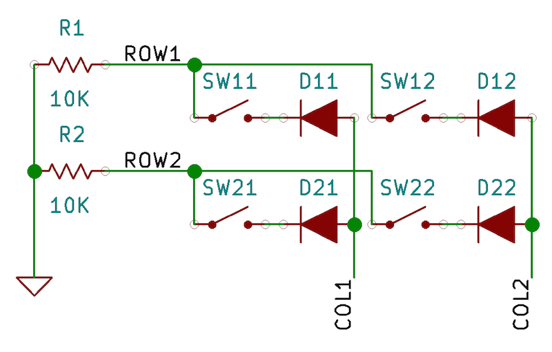
Our keyboard is still quite limited. To enhance its functionality, we need to incorporate keys and arrange them into a keyboard matrix. A standard 104-key keyboard might have 18 rows and 6 columns, but for our initial setup, we’ll use a simple 2x2 keyboard matrix. Here’s the schematic:
And here’s how it looks on a breadboard:
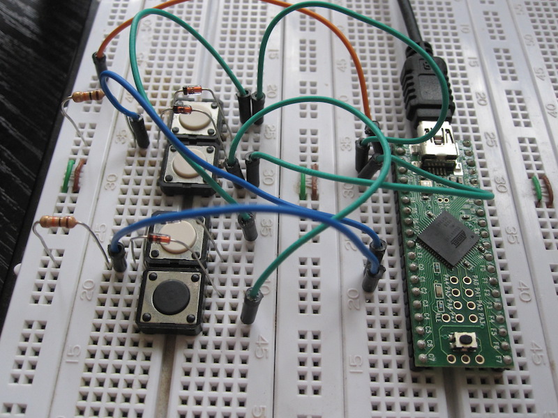
Assuming ROW1 connects to PINA0, ROW2 to PINA1, COL1 to PORTB0, and COL2 to PORTB1, the scanning code would be:
| |
The code scans each column sequentially, reading the state of every key switch within that column. This information is then stored in an array. Our CALLBACK_HID_Device_CreateHIDReport() function utilizes this array to send the corresponding scan codes based on the key switch states.
Phase Three: A Two-Part Keyboard
We’ve now created a basic keyboard, but our goal is advanced ergonomics. To accommodate two hands, let’s add another keyboard half.
This second half will have its own keyboard matrix, functioning identically to the first. The interesting aspect is the communication between the two halves. The most common protocols for connecting electronic devices are SPI, I2C, and UART. For this project, we’ll utilize UART.
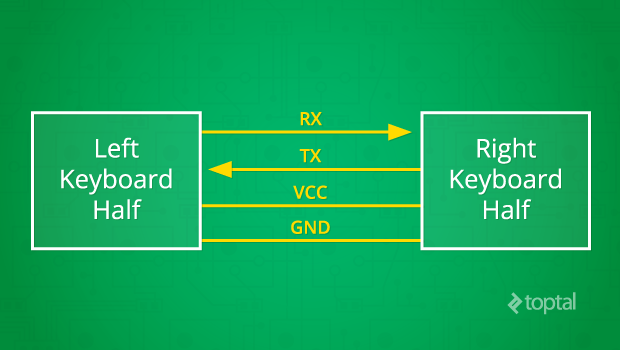
As per the diagram, bidirectional communication occurs with RX transmitting data rightward and TX leftward. VCC and GND provide the necessary power. Both UART transceivers must be configured with the same baud rate, data bits, and stop bits. Once configured, communication can begin.
In this setup, the left keyboard half transmits one-byte messages to the right half via UART, indicating key press or release events. The right half processes these messages, updating the state of the complete keyboard matrix array in its memory accordingly. Here’s how the left half sends messages:
| |
The right half’s code for receiving these messages is as follows:
| |
When a byte arrives via UART, the KeyboardRxCallback() interrupt handler is triggered. Since interrupt handlers need to execute quickly, the received message is placed into a ring buffer for later processing. The main loop eventually processes this buffer, updating the keyboard matrix based on the received messages.
While this demonstrates the basic principle, the final protocol will be more sophisticated, handling multi-byte messages and verifying message integrity using CRC-CCITT checksums.
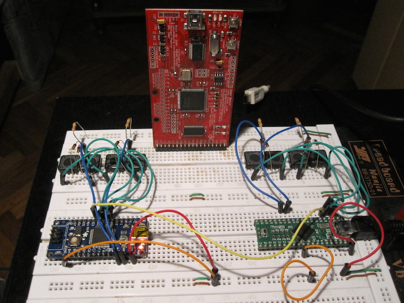
Our breadboard prototype is now quite impressive:
Phase Four: Introducing the LED Display
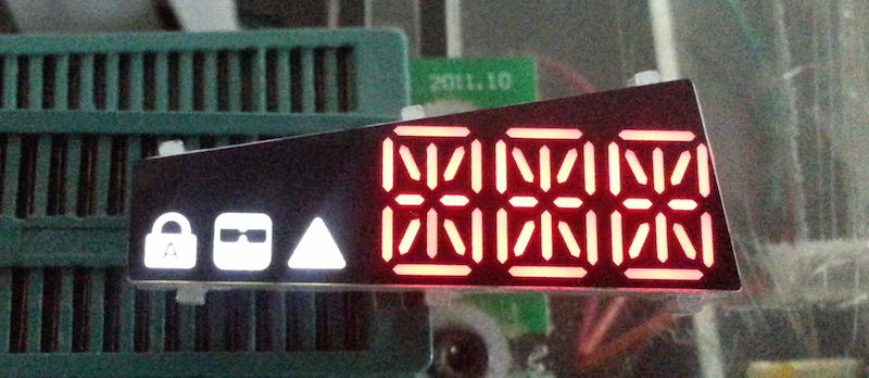
One of the UHK’s key features is the ability to define multiple application-specific keyboard maps for enhanced productivity. To inform the user of the active keymap, an integrated LED display is incorporated into the keyboard. Here’s a prototype display with all LEDs illuminated:
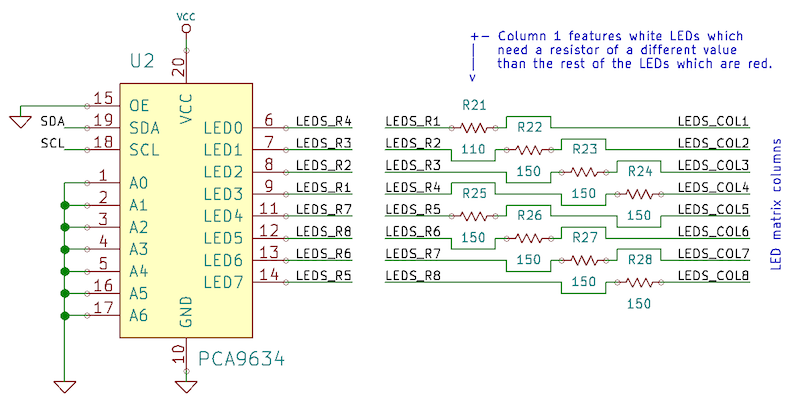
The LED display is implemented using an 8x6 LED matrix:
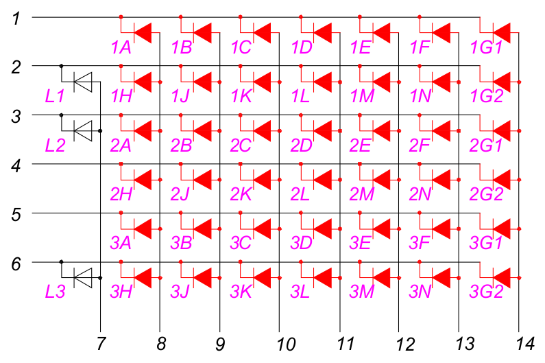
Each pair of red LED symbols represents the segments of one of the fourteen-segment LED displays. The white LED symbols represent the three additional status indicators.
To illuminate an LED, the corresponding column is set to high voltage, and the corresponding row to low voltage. An interesting consequence of this system is that only one column can be enabled at any given time (all LEDs to be lit on that column have their corresponding rows set to low voltage), while the other columns remain disabled. One might assume this would lead to flickering, but the rapid updating of columns and rows renders it imperceptible to the human eye.
Two integrated circuits (ICs) control the LED matrix: one for the rows and one for the columns. The PCA9634 I2C LED driver acts as the source IC, controlling the columns:
The TPIC6C595 power shift register serves as the sink IC, managing the rows:
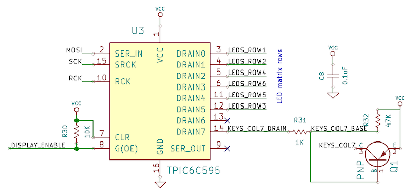
Let’s take a look at the relevant code:
| |
LedMatrix_UpdateNextRow(), called approximately every millisecond, updates one row of the LED matrix. The LedStates array, containing the state of each LED, is updated via UART based on messages from the right keyboard half, similar to the key press/release event handling.
The Complete Picture
We’ve now established all the essential components for our custom hacker keyboard. Let’s step back and view the complete system. The keyboard’s interior resembles a miniature computer network, with numerous interconnected nodes. However, these nodes are not full-fledged computers, but rather tiny integrated circuits, and the distances between them are measured in centimeters, not meters or kilometers.
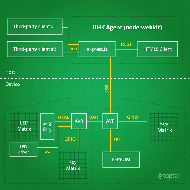
While we’ve extensively discussed the device-side aspects of the developer keyboard, we haven’t delved much into UHK Agent, the host-side software. This is because, unlike the hardware and firmware, Agent is still in its early stages. However, we have determined Agent’s high-level architecture, which I’m happy to share.
UHK Agent is the configuration application used to customize the keyboard according to user preferences. Despite being a rich client application, Agent leverages web technologies and operates on the node-webkit platform.
Agent communicates with the keyboard via the node-usb library, sending specific USB control requests and processing their responses. It utilizes Express.js to provide a REST API for third-party application integration and Angular.js to create a user-friendly interface.
| |
Each command consists of an 8-bit identifier and a set of command-specific arguments. Currently, only the re-enumerate command is implemented. The sendReenumerateCommand() function instructs the device to re-enumerate as either the left bootloader, the right bootloader (for firmware upgrades), or as a keyboard device.
To illustrate the advanced features this software will enable, here are a few examples: Agent will visualize the wear on individual keys, notifying users of their expected lifespan and prompting them to purchase replacements for impending repairs. It will also provide a user interface for configuring various keymaps and layers, as well as adjusting mouse pointer speed, acceleration, and countless other powerful features. The possibilities are truly limitless.
Prototype Development
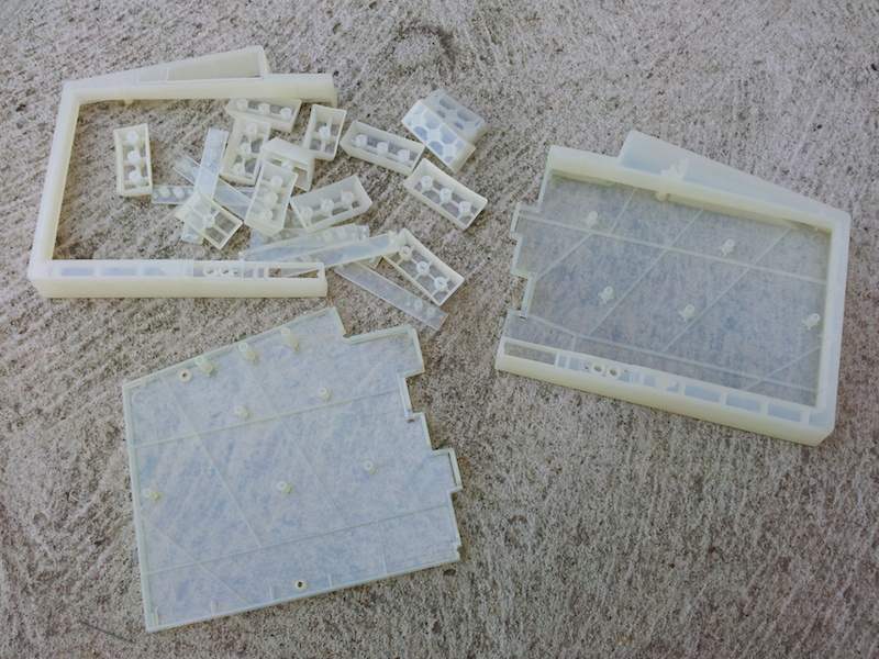
Creating custom keyboard prototypes is a labor-intensive process. It starts with finalizing the mechanical design, which is complex in itself, involving custom-designed plastic components, laser-cut stainless steel plates, precision-milled steel guides, and neodymium magnets to secure the two keyboard halves. Every element is meticulously designed in CAD before fabrication.
Here’s a glimpse of the 3D printed keyboard case:
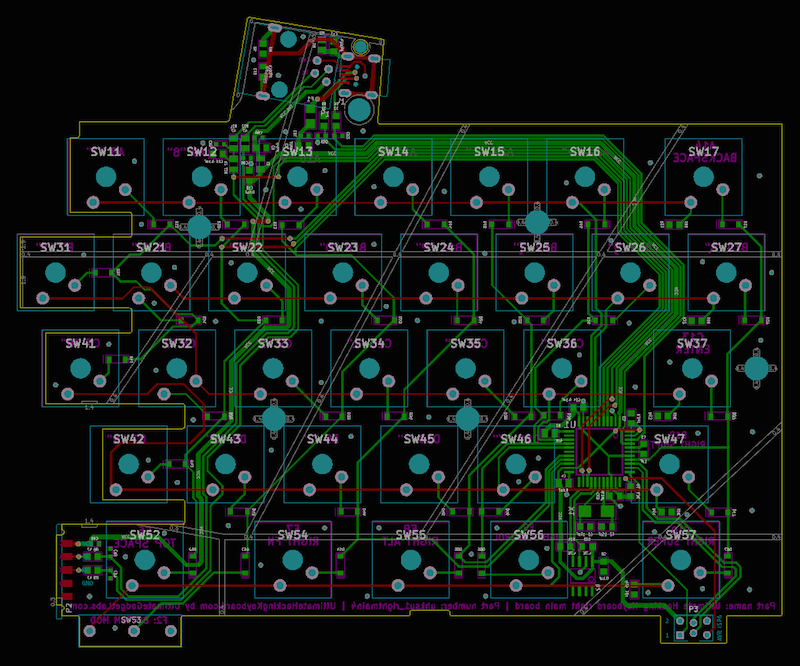
Based on the mechanical design and schematic, the printed circuit board (PCB) is designed. Here’s the right-hand PCB in KiCad:
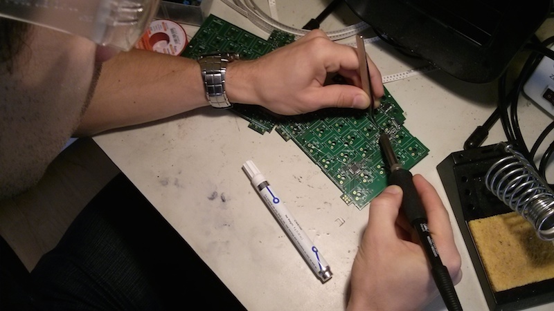
Once the PCB is fabricated, the surface-mounted components are soldered by hand:
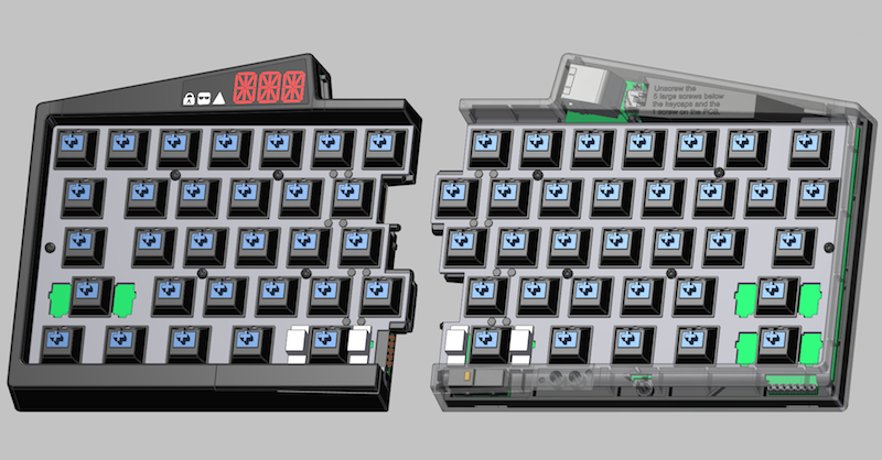
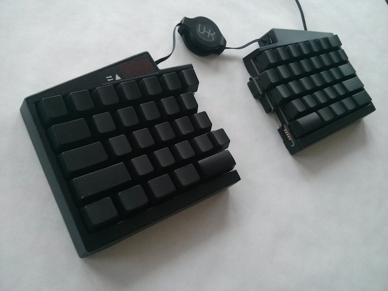
Finally, after manufacturing all the parts, including 3D printing, polishing, painting the plastic components, and assembling everything, we arrive at a functioning hacker keyboard prototype:
Conclusion
I often compare developers’ keyboards to musicians’ instruments. Keyboards are deeply personal tools that we use daily to meticulously craft the software of tomorrow, one character at a time.
Perhaps that’s why developing the Ultimate Hacking Keyboard feels like such a privilege. Despite the challenges, it has been an exhilarating journey and an incredibly enriching learning experience.
This is a vast subject, and I’ve only scratched the surface here. I hope this article has been both enjoyable and informative. Feel free to ask any questions in the comments.
Finally, I encourage you to visit https://ultimatehackingkeyboard.com for more information and to subscribe for updates on our upcoming campaign launch.