The previous Beolover Blog post concluded with a functioning Beomaster 2000 (Type 2801) amplifier and verified key voltages. However, the display lamps needed replacement due to burnouts, and the tuning dial cord was significantly frayed. These parts had to be ordered.
With the arrival of the new parts, the restoration process resumed, starting with the dial cord replacement, considered the most challenging task based on the service manual’s instructions.

A high-quality black radio dial cord, measuring 0.028 inches in diameter, was obtained from Bob’s Antique Radio & Electronics. This non-stretch nylon cord with a fiberglass core came in a 25-foot length, exceeding the required 44 and 7/8 inches (114 centimeters) for the Beomaster.
Since the existing frayed cord used knots to connect to the tuning dial pulley’s spring mechanism, research was conducted on similar radio repairs. The chosen approach involved creating a replacement cord with knots at each end, resulting in a stretched length of 44 7/8 inches between the knot apexes.
“Perfection loop” knots were chosen for this purpose.

This particular knot diagram was favored as it clearly illustrated the apex points for the 114-centimeter measurement.
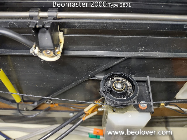
After the knotting, the cord was wound around the dial components as per the service manual’s guidance, and the loops at each end were secured to the spring mechanism’s hooks.
Pictures of the restrung dial cord are included below.


The next stage involved the display board, which houses four lamps: Power On, FM Stereo, Tuning Balance 1, and Tuning Balance 2.


The outdated double-sided foam tape was removed and substituted with new 3M double-sided tape. Images show the display board with new lamps from Martin Olsen installed.

The dial pointer lamp also required replacement and presented a challenge. This lamp is crucial as it controls power to all other display lamps. A fault in this lamp would render the others non-functional.
The dial point assembly had undergone prior repair attempts, evident in the glue and tape holding it together.


Lamp replacement necessitated careful disassembly of the glued casing. Thankfully, the salvaged pieces seemed reusable for rebuilding the dial pointer assembly.

In a fortunate turn of events, Martin Olsen had a compatible Beomaster 2000 (Type 2801) dial pointer assembly available, which is currently en route. Meanwhile, testing continued using a temporary lamp holder setup with the replacement dial pointer lamp. This enabled the Beomaster to power on and confirmed the functionality of the other lamps.

With the lamps now operational, focus shifted to a new issue: the inability to tune in FM stations. A brief burst of sound would occur, then silence. Disabling the muting switch revealed faint stations (without stereo), but the audio would cut out as soon as tuning was refined.
Monitoring the FM mute signal revealed it remained active (around 22V) when a station was tuned, but dropped to approximately -8.3V when switched to Tape input.
The Beomaster 2000 utilizes a source muting circuit to silence the preamplifier audio to the output amplifier during source selection. Additionally, an FM muting control signal engages with the audio mute during station tuning. The Beomaster 2000 features a switch to toggle FM station muting, but it had no effect in this scenario. FM audio remained muted.
Below are two schematic diagrams of the Beomaster 2000 FM muting circuit: one from the service manual and another illustrating the actual wiring of this unit.

The service manual identifies trimmer resistor 2R40 as the FM muting circuit adjustment point. This seemed a logical starting point, except it was absent on this particular Beomaster 2000.
The right-hand circuit diagram reflects the actual PCB 2 layout. This suggests this Beomaster unit might be an earlier model or version, while the service manual depicts an updated circuit.
The FM Detect Balance and Indicator Balance circuits, also shown in the diagram, are related to the FM muting circuit. Both have trimmer resistors for adjustments. Manipulating these resulted in some FM station tuning and affected the problematic FM muting signal.
A visual inspection of PCB 2 in the relevant schematic area is shown below.

Trimmers 2R28 and 2R31 showed signs of deterioration. They were replaced, and subsequent testing revealed dead spots in the old components. Transistors 2TR6, 2IC2, and 2IC3 were checked and found to be in good condition.
The three tantalum capacitors (2C20, 2C51, and 2C52) in this section were then checked. While spot checks earlier had shown no issues, these three 0.1uF capacitors measured around 0.07uF when desoldered, indicating a 30% deviation from tolerance.
The decision was made to replace trimmers 2R28 and 2R31, along with the three 0.1uF tantalum capacitors. The board’s appearance after these replacements is pictured below. An oscilloscope probe is connected to the FM muting signal for monitoring purposes while adjusting trimmers 2R28 and 2R31.

A closer view of the FM muting circuit components on PCB 2 is provided below.

These modifications allowed for successful adjustment of the FM Detect balance and FM Indicator balance trimmers. A tuned station now displays evenly on both tuning balance lamps, the FM stereo light functions as intended, and the audio muting circuit operates correctly.
Further checks are planned. The replacement tuning pointer assembly, once received, will be installed.
An additional observation requires attention: when switching from FM to Phono or Tape, the lower tuning balance lamp (IL2) illuminates fully, matching the Beomaster 2000 Power On lamp. It is unclear if this is normal behavior. Intuitively, neither FM indicator lamp should be lit when Phono or Tape is selected. The Tape source functions correctly, and FM stereo stations are received without issue. No adjustments for this indicator lamp, aside from the balance trimmers (currently set for balanced FM reception), have been identified.
Further investigation is needed to determine the signal triggering IL2 illumination when Tape or Phono is selected.