This article details the restoration of a Beogram 4002 turntable from Kentucky. The unit, pictured below, was in excellent condition, making it ideal for a complete refurbishment.

As is typical with DC motor Beograms, the platter motor was the starting point. These motors commonly suffer from dried-out bearings, leading to speed instability. The extracted motor is shown here:

The motor was disassembled to access the bearings:

The bearings, visible as two small rings on the black pad, were then submerged in motor oil under a vacuum:

The resulting bubbles indicated air being pulled from the bearings, allowing oil to penetrate. This process typically lasts 48 to 72 hours. Other restoration tasks were addressed while this took place.
The arm lowering and carriage transport mechanisms were rebuilt, starting with the original setup:

All parts were removed:

and cleaned ultrasonically:

The parts, now clean, were ready for reassembly:

A new rubber gasket replaced the old one in the damper assembly:

This addressed potential arm lowering inconsistencies. The reassembled setup is depicted here:

The old, cracked plastic carriage pulley was replaced with a new aluminum version:

An LED assembly replaced the incandescent bulb in the tracking sensor. This is the original setup:

The housing was removed, exposing the tracking sensor aperture:

The old and new assemblies are shown side-by-side:

The new LED assembly was installed:

A trimmer on the assembly enables brightness adjustment for calibration.
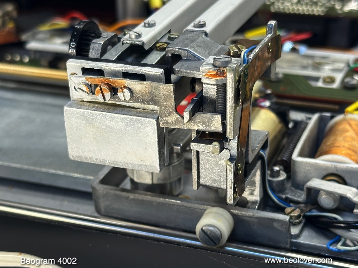
The damper-to-arm linkage, crucial for smooth operation, was then lubricated. This linkage is attached to the sensor arm assembly, visible here:
The sensor arm was removed, followed by the linkage:

The small copper plate was cleaned, reattached with epoxy, and the linkage’s pivot point was lubricated before reassembly.
Attention turned to the electronics. The aging power Darlington transistors on the main PCB were replaced with TIP102 and TIP107 transistors to ensure stability. Here’s the original TIP120:

A 100nF capacitor was added between the emitter and ground to address potential high-frequency oscillations:

The board was then removed, revealing its original state:

A closer look at the ‘RPM section’:

All electrolytic capacitors, power transistors, the RPM relay and trimmers, and the sensor arm transistor and resistor were replaced:

The refurbished RPM section now included a new relay and trimmers:
[ ](https://blogger.googleusercontent.com/img/b/R29vZ2xl/AVvXsEhPkphXwDH-F-YQKMz8dx3BB