Following the replacement of the tracking sensor’s light source, the next stage in restoring my Beogram 4002 (5521) involved addressing the incandescent bulbs within the RPM trimmer panel. The 33 RPM bulb had burned out, prompting the decision to replace both bulbs with custom-designed SMD LED assemblies. Recognizing the importance of a red light component for illuminating the red RPM indicators, red-green LEDs were chosen. While amber LEDs offer an incandescent-like aesthetic, their narrow wavelength distribution hinders their ability to effectively illuminate red surfaces. The image showcases the compact circuit boards housing the LEDs along with two current limiting resistors, one for each color (red and green), enabling adjustments to their relative intensities for an authentic lighting effect.

A recently created video demonstrates the process of replacing the bulbs with these boards. These boards are available to other enthusiasts - simply send an email to inquire.
Here are some impressions of the installation process on this specific Beogram. This first image shows the trimmer panel after removal:
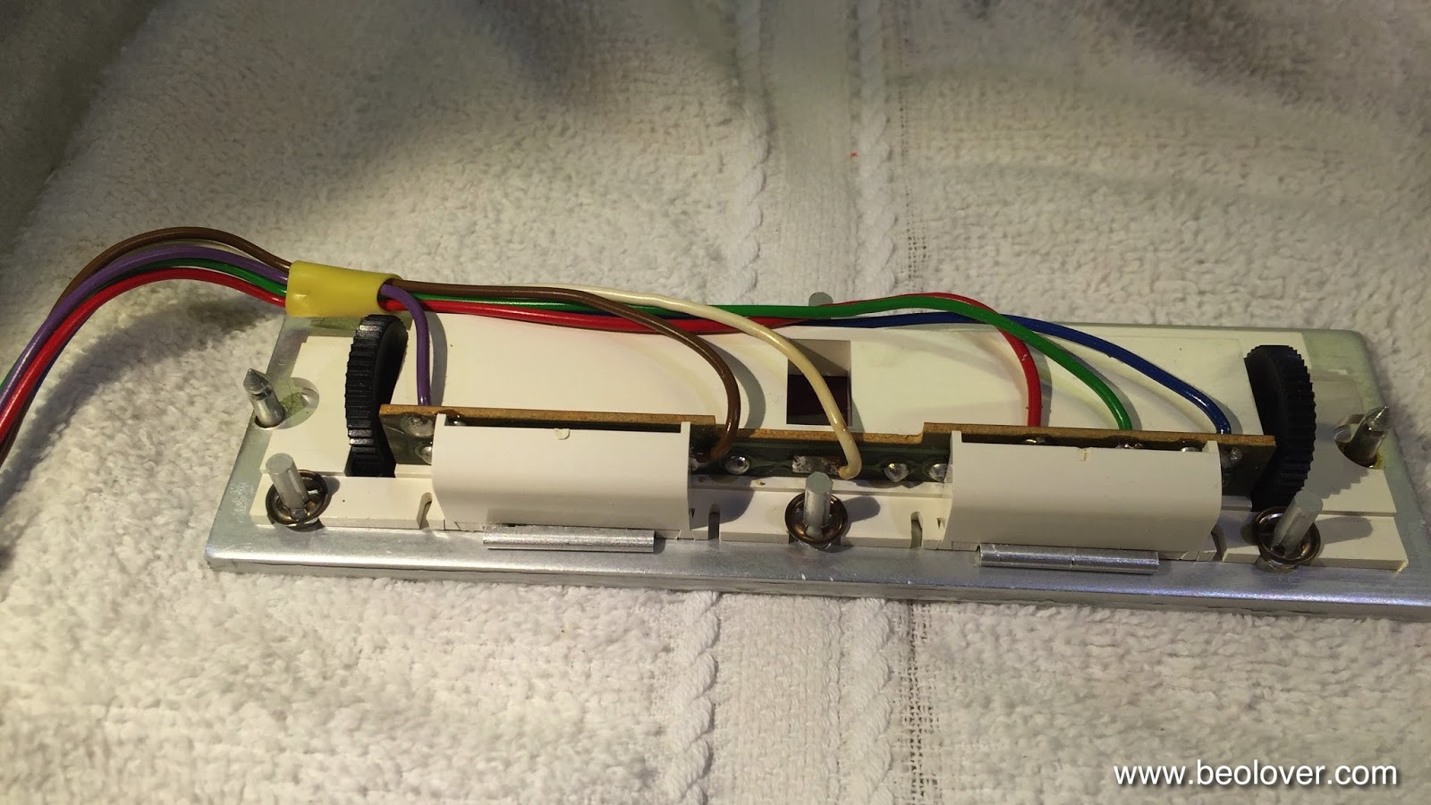
Access to the bulbs is achieved by removing the two covers:

After desoldering the leads, the bulb assemblies can be slid out:

The PCBs can now be installed, ensuring they sit flush with the aluminum surface:

Finally, replace the covers:

And there you have it!