During the summer of 2019, I had the opportunity to work on a Beogram 4002 turntable from Virginia, specifically restoring its DC platter motor. I recently received the entire unit for a complete overhaul. The arm lowering mechanism had been previously restored and was in excellent condition. My attention turned to the remaining areas needing restoration.
To begin, I tackled the main PCB. The first photo illustrates its original condition:

My restoration efforts included replacing all electrolytic capacitors, installing a new RPM relay, and adding new 25-turn RPM trimmers:

Next, I addressed the record detection circuit. Based on recent experiences with similar restorations, I’ve made it a practice to replace TR4, the transistor responsible for sensor signal amplification. The original transistor (BC183C) is shown here:

This transistor is prone to being out of spec, often exhibiting low gain, which can be risky for the stylus. If amplification fails, the record detection circuit becomes unreliable. I replaced it with a modern high-gain 2N5089 transistor. I also installed a 25-turn 5 MOhm trimmer as the bias resistor. To facilitate adjustment with the board powered, this trimmer needs to be initially placed on the solder side:

Following the manual’s recommendation, I adjusted the collector voltage to 4V. With the voltage set, I moved the trimmer to the component side, placing it next to the new transistor:

With that, the main PCB restoration was complete:

I then replaced the main dual capacitance reservoir capacitor. Two modern single capacitors, secured with a 3D-printed fixture, replaced the original:

Accessing the output PCB required removing the keypad:

On the output PCB, I replaced the output relay and the capacitor that dictates the relay’s timing. Additionally, I incorporated a red switch to connect the system and signal grounds, addressing potential hum issues:

With the keypad already removed, I took the opportunity to replace the light bulbs in the RPM trimmer panel with LED boards. The panel is pictured here with the original bulbs:
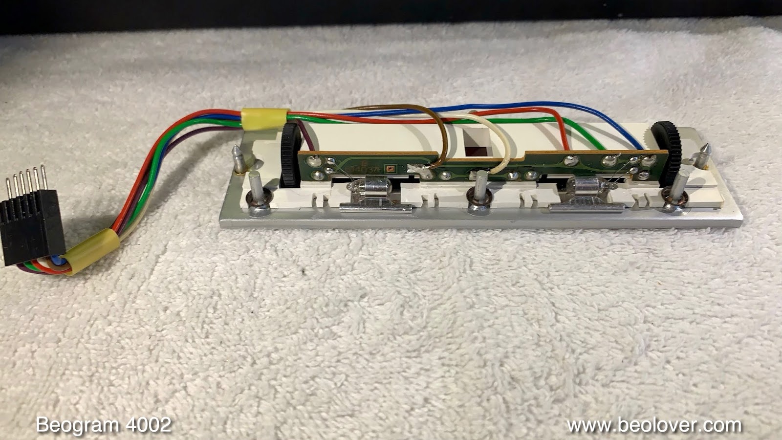
And here with the plug-in LED boards:

The panel in operation:

The chosen red-green LEDs provide an incandescent-like glow. Red indicators are properly illuminated thanks to the red component. Orange LEDs would result in grayish indicators because they lack red photon emissions.
Next on my list was replacing the tracking sensor’s light bulb. The original black bulb housing is shown here:
![]()
Here’s the replacement part alongside the original assembly:
![]()
The LED is positioned where the original light bulb’s filament was located. Here’s the LED assembly during the tracking feedback calibration:
![]()
Fine-tuning the tracking feedback is made easier with the blue trimmer, which adjusts the LED’s brightness.
This particular Beogram 4002 still had its original plastic pulley. These pulleys are known to become brittle and break:

I replaced it with a durable, precision-machined aluminum pulley provided by a fellow B&O enthusiast in Vienna:

It looks fantastic! If you’re interested in one for your Beogram, I’d be happy to connect you with the supplier. Feel free to email me or use the contact form.
The transport lock bushings are another set of plastic components susceptible to deterioration in this Beogram 4002 model. A telltale sign of their degradation is an “orangish” appearance. This Beogram exhibited this same issue:
![]()
All three bushings were removed:
![]()
And I replaced them with robust nylon bushings, 3D-printed using SLS technology. The bushings are designed in two parts. One part is inserted from the bottom:
![]()
And the other from the top:
![]()
The left bushing installed:
![]()
And the top retaining plate secured:
![]()
With the transport locks rebuilt, I moved on to the last remaining incandescent bulb in the sensor arm:

The bulb was replaced with an LED circuit on a flexible PCB designed to fit within the bulb compartment. It draws a current similar to the original bulb, ensuring the circuit recognizes a functioning light source. Here’s the installed assembly:
 ](
](