This unit is currently for sale. Please, see here.
This post details the complete restoration of a Beogram 4002 (5513) from Arizona, which I first inspected as shown here. The unit’s condition upon arrival is pictured below:

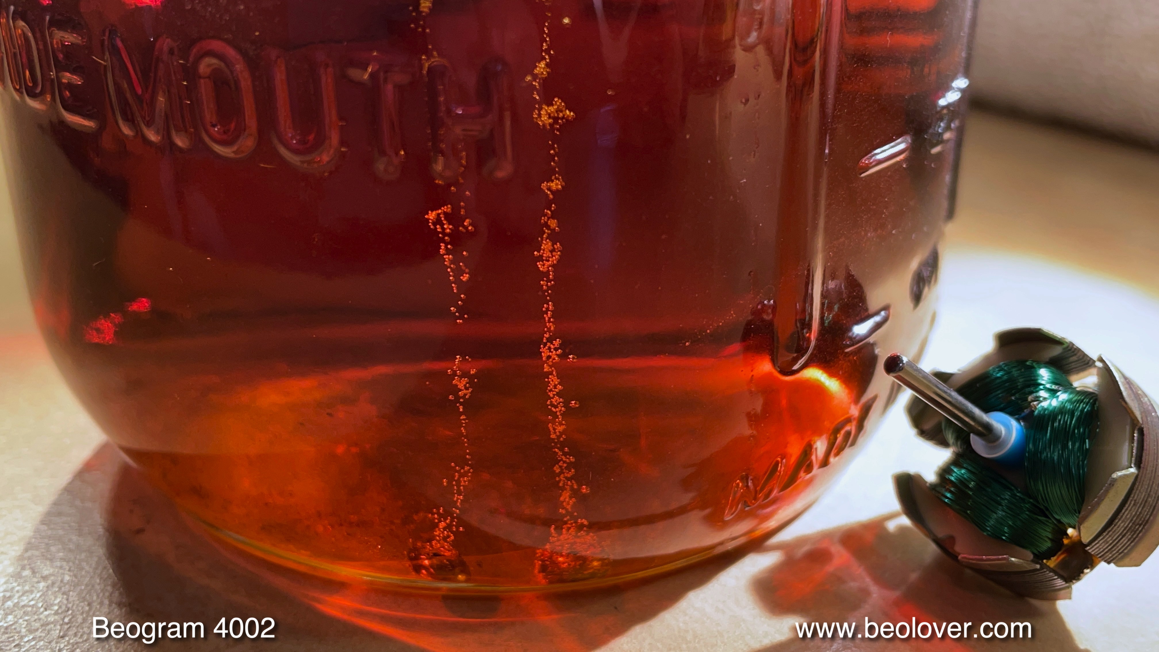
My first step, as always, was to initiate oil infusion for the platter motor bearings. Here’s the motor after removal:

I took it apart to extract the bearings (two small rings on the black pad):

I then submerged the bearings in motor oil and created a vacuum. Bubbling began immediately as the vacuum removed air from the bearing material’s pores, allowing fresh oil to seep in:
While the infusion took place (typically 2-3 days until bubbling ceases), I removed the moving parts of the arm lowering and carriage transport systems for cleaning and lubrication:

The cleaned parts are shown below:

Once the mechanisms were back together, I switched out the cracked plastic carriage pulley for a machined aluminum copy:

Next, I replaced the tracking feedback mechanism’s incandescent bulb with an LED replacement. In the picture, the black box indicates the original part’s location:
![]()
Here’s the replacement. The blue component is an adjustable trimmer for fine-tuning the LED’s brightness, helpful for calibrating the tracking:
![]()
The final stage of carriage restoration involved removing the damper-to-tonearm linkage to lubricate its pivot point. This required removing the sensor arm. Pictured is the rear view of the assembled arms:

The sensor arm assembly was then removed:

as was the linkage:

The small copper plate, responsible for reducing lateral arm friction when raised, was barely attached and detached easily. This is a common issue:

Normally secured with double-sided tape, which deteriorates over time, I reattached it using epoxy:

With that, work on the carriage and arm lowering mechanism was finished. Next came the main PCB rebuild. Having encountered several units with failed power transistors and Darlingtons, I’ve made it standard practice to replace them. Apparently, “silicon is forever” isn’t entirely accurate! It’s best to replace the two top-side transistors while the board is secured. This image shows the original TIP107 Darlington (1IC4) controlling the solenoid:
![]()
I replaced it with a new TIP107:
![]()
The board was then removed. Here’s the component side in its pre-restoration state:

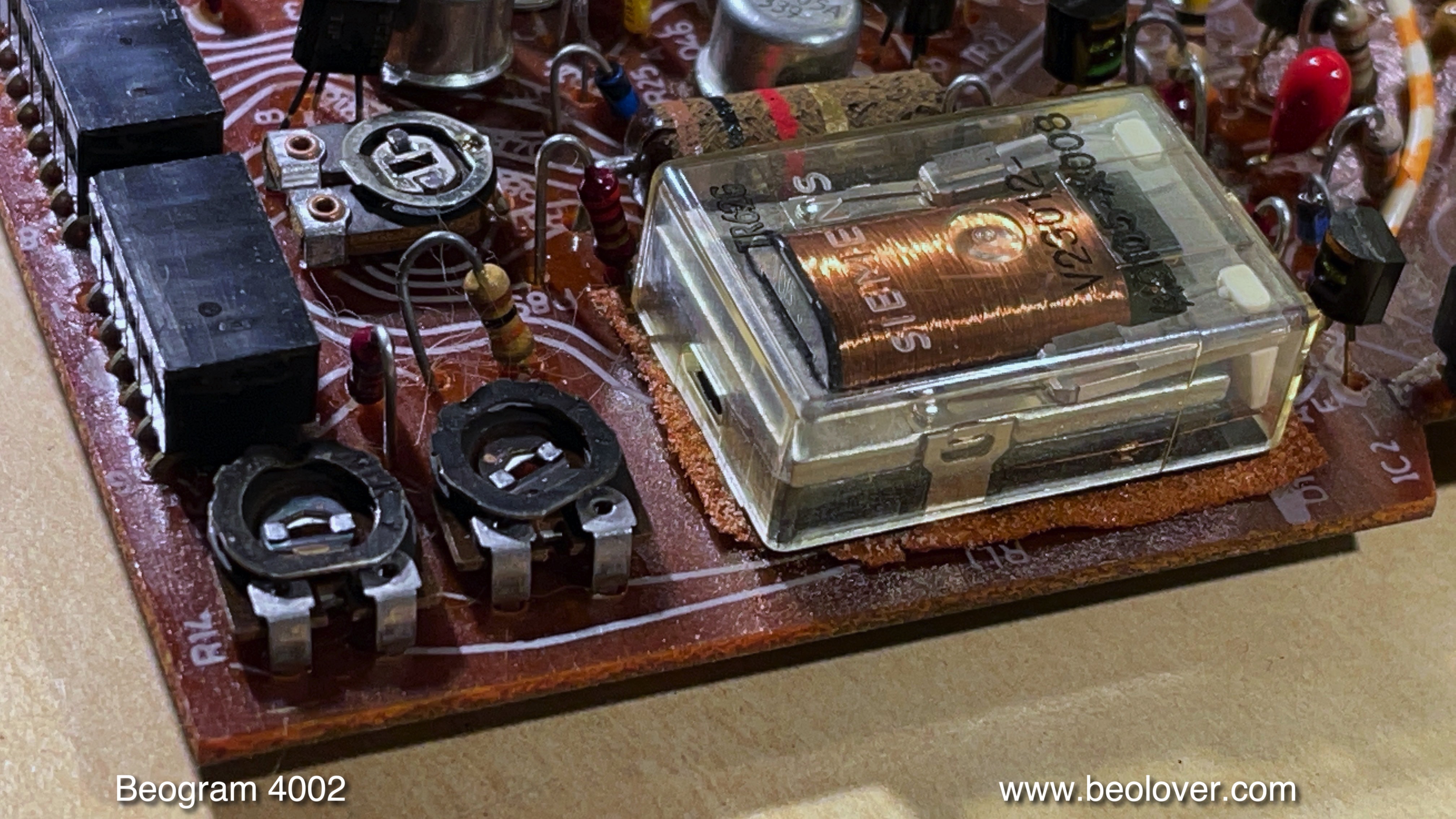
This close-up highlights the original RPM section, with the Siemens RPM switch relay and two trimmers for speed adjustment:
I replaced all electrolytic capacitors, the entire RPM section, the sensor arm circuit, and the transistor powering the platter motor:

The rebuilt RPM section is pictured here. I opted for 25-turn encapsulated trimmers, enabling more precise RPM adjustment:
[![](https://blogger.googleusercontent.com/img/b/R29vZ2xl/AVvXsEisyH3sU4zRr9E2kTb5ElmK5fckO0QJbemN8fWPNwMjt–u0YF7bCVtwN4iPIOytc2SPu9_rjZxEWfoEa0I067tHH8bQX5st4Rh8i1yYkcm9oWLCkMGOOWwwxn-9-dUy93te7xlXly4R