I’m restoring a Beogram 4002 Type 5503 turntable from California. This second-generation model uses an AC motor and has the same optical carriage position detection as the later DC motor versions. My initial assessment of the unit before restoration can be found on my blog. I offer the parts I use in my restorations to other enthusiasts – contact me via email or my contact form if interested.
The first step in any Beogram 400x restoration is cleaning and re-lubricating the arm lowering mechanism. The old lubricants harden over time, restricting the arm’s movement.

I disassembled the mechanism

and cleaned each part. I typically lubricate the damper with motor oil and the pivot points with synthetic grease.
Next, I addressed the damper to tonearm linkage, which is another area prone to sticking:

This step involves removing the sensor arm. During reassembly, it’s crucial not to lose the small spring located beneath the circlip securing the linkage to its pivot shaft. After reassembly, I adjusted the arms to be orthogonal to the carriage and parallel to one another:

Continuing with the carriage and arm mechanism, I installed a new tracking sensor light source. This consists of a 3D-printed housing, an LED, and a trimmer for brightness adjustment:
![]()
Here it is installed:
![]()
To complete the carriage mechanism restoration, I cleaned and re-lubricated the spindle. I also replaced the old, cracked pulley with a new precision-machined aluminum one (sourced from an enthusiast in Vienna – contact me for information).

Next, I rebuilt the electronics. I replaced all the capacitors

and installed new 25-turn RPM adjustment trimmers.

The record detection circuit received an upgrade with a new high-gain transistor and a 5MOhm trimmer. This allows for precise adjustment of the amplifying transistor’s working point.

Here’s a view from the solder side:

I adjusted the transistor’s working point to the recommended 4V.

Next, I replaced the reservoir and motor phase capacitors,

using a 3D-printed assembly to neatly house the new, smaller capacitors.

During a preliminary test with the platter installed, the AC motor made a knocking sound. I removed and disassembled it to perform an oil infusion on the bearings.
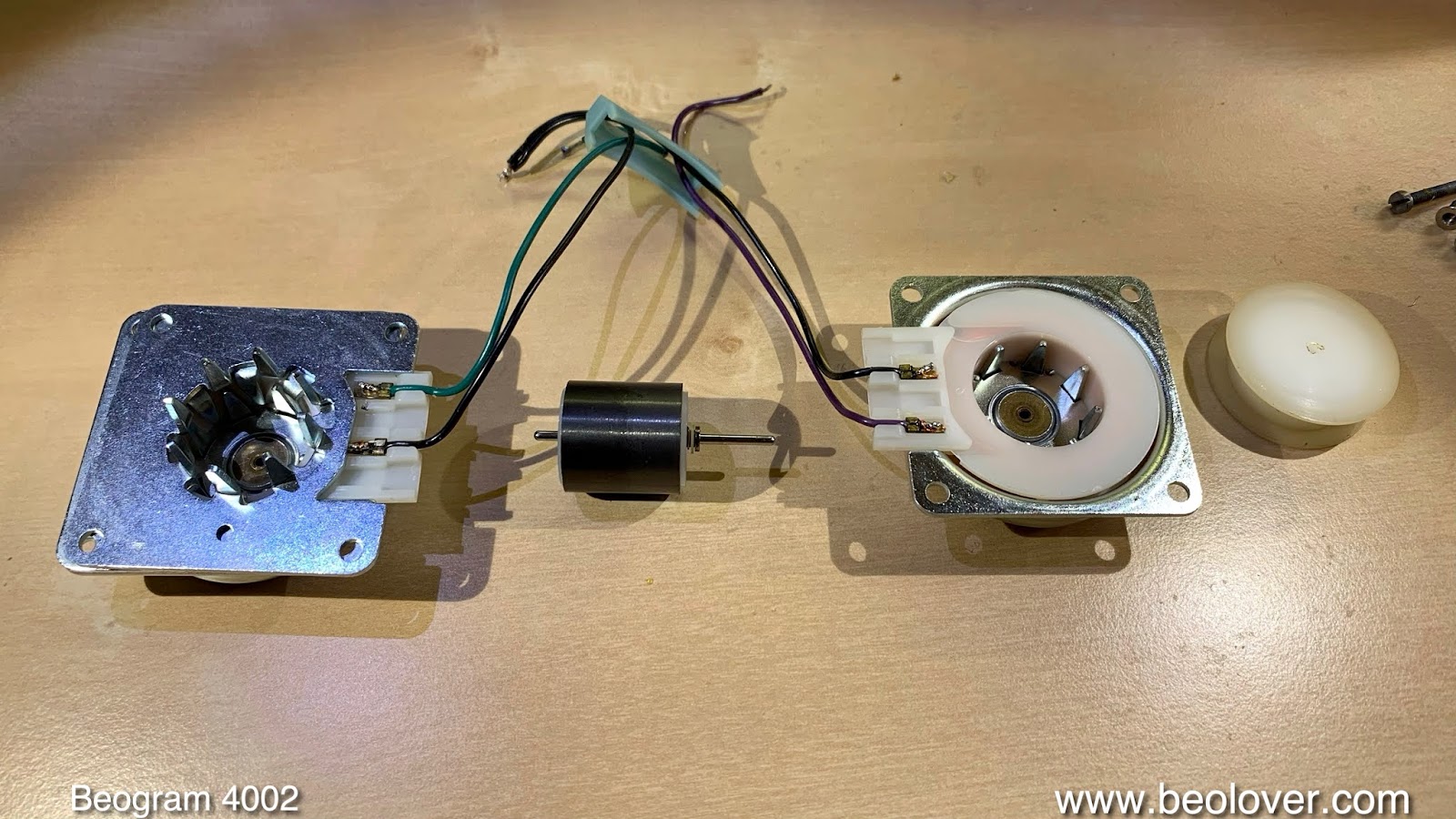
It’s challenging to remove the bearings from their housings, so I submerged the entire assembly in oil.

After letting it soak for a day, I reassembled and reinstalled the motor.
I then turned my attention to the keypad. I removed the output PCB to replace the output relay with a new encapsulated unit and to replace the capacitor responsible for relay delay. I also added a switch for connecting the system and signal grounds, if needed. This often resolves humming issues.

Next, I replaced the incandescent bulbs in the RPM panel with LEDs. The heat generated by the original bulbs can affect the user-adjustable RPM trimmers in the panel, impacting RPM stability. Here are the LED replacements:

They are direct replacements for the original bulbs.

While testing the LEDs, I noticed the 33 RPM trimmer indicator had a wavy white reflective background.

This is another issue caused by heat from the original bulbs. I disassembled the panel. Here’s the wavy background sticker:

I replaced it with a piece of white insulating tape cut to size:

Then I reassembled the panel:

It looks great now – no more waviness!
The final bulb to replace was in the sensor arm. Here’s the original bulb alongside the Beolover LED replacement circuit, which is built on a flexible printed circuit board:

This replacement uses a warm-white LED and a resistor to mimic the original bulb’s power consumption, which is necessary