This ESP8266 Arduino guide is designed to introduce you to embedded programming using Arduino on a chip that has gained immense popularity among makers and developers alike. Its popularity stems from its affordability and user-friendliness in the IoT domain. We’ll also delve into some unofficial techniques to control Alexa within a home environment. However, remember that these techniques are intended for personal demonstrations only and are not suitable for production environments.

What makes this approach particularly appealing is its ability to automate practically any electrical appliance within our homes using Alexa. Moreover, we gain valuable experience in embedded programming with Arduino, a skill not as widespread among modern programmers. Lastly, we’ll be working with the acclaimed ESP8266 chip, a favorite among DIY enthusiasts. This compact chip, equipped with built-in Wifi, is capable of managing a variety of tasks, making it perfect for this project as it facilitates direct communication between Alexa and the chip.
Before we dive in, let’s understand how Alexa programming typically works:

- You issue a voice command to your Alexa device.
- Alexa transmits your speech to Amazon’s cloud infrastructure.
- The command is then directed to a corresponding Alexa “skill” - a program operating within Amazon’s cloud.
This Alexa “skill” then processes your command. Usually, this results in a response being sent back to your Alexa, prompting it to reply vocally. For Alexa IoT, the command is routed to a “device shadow” in Amazon’s cloud, eventually leading to a response being sent to a designated device in your home. However, our method bypasses this entire cloud interaction. Our aim is to enable direct communication between Alexa and our ESP8266 chip within our home network, without relying on external cloud services.
The method we’ll employ is not exactly a secret. We’ll configure our ESP8266 to “emulate” a Wemo Belkin, a device specifically authorized by Amazon to interact directly with Alexa devices. This circumvents the cloud-based communication we discussed earlier.
By posing as a Wemo device, our ESP8266 gains the privilege of receiving commands directly from Alexa.
ESP8266 Arduino Tutorial: The Plan
- Our ESP8266 will be programmed to detect probe signals sent by Alexa on the local Wifi network, searching for compatible devices. The ESP8266 will respond to these probes by identifying itself as a Wemo device.
- Once the Alexa device establishes trust, our ESP8266 will listen for subsequent commands, specifically to control our TV using IR codes transmitted via an IR transmitter.
What You’ll Need

You’ll need to gather a few items beforehand, all readily available:
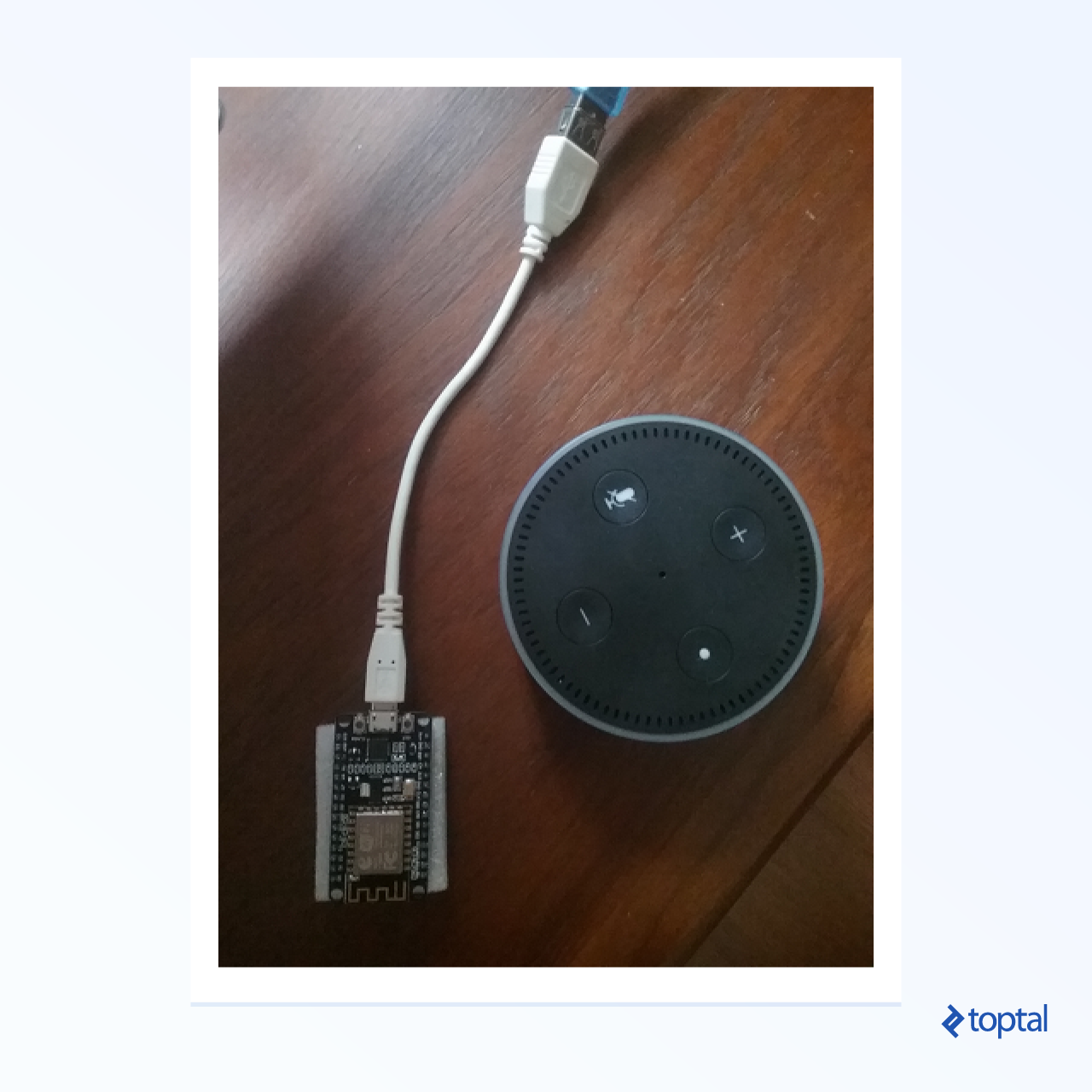
- Any Alexa-enabled device will do. This guide was developed using an Alexa Dot. Will it function with an Echo simulator? Possibly! (Though, it hasn’t been tested). Feel free to experiment if you’re adventurous (or budget-conscious). While an Alexa device costs a bit, using Echosim is free.
- An ESP8266 chip is essential, costing only a few dollars at the time of writing. You can find these on Ebay or any well-equipped online electronics store.
- An IR (infrared) diode is necessary. You’ll connect this to your ESP8266, handling the wiring yourself. For our purposes, we only need its transmitting capabilities; receiving IR signals is not required. For this tutorial, ensure you connect the diode to GND and output 0. (Different wiring configurations are acceptable, but require modifying the code accordingly. This link may help you. Keep in mind that on the ESP8266, pin 0 might be labeled “D3”.)
- A serial adapter is needed to connect your computer to the ESP8266. It should have a USB connector on one end and a compatible connector for your ESP8266 on the other.
- Finally, you’ll need access to a local wifi network and know its username and password.

Software Setup for Arduino
- Install the Arduino IDE, available for all major operating systems, including Windows. This guide utilizes the Ubuntu version, but the Windows version works seamlessly as well.
- You’ll need the ESP8266 development library for Arduino.
- Driver installation is typically unnecessary as most adapters are plug-and-play.
Putting it All Together
- Install Arduino IDE.
- Install the ESP8266 library using the Boards Manager.
To install the ESP8266 library via the Boards Manager:
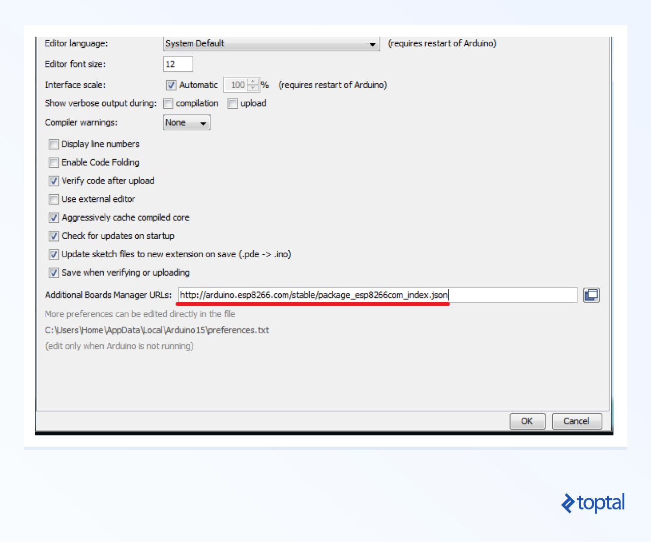
- In the Arduino IDE, navigate to File -> Preferences.
- Locate the “Additional Boards Manager URLs” field and paste this URL: http://arduino.esp8266.com/stable/package_esp8266com_index.json
- Confirm by clicking OK.
Open the Boards Manager by going to Tools -> Board: [current board] -> Boards Manager.
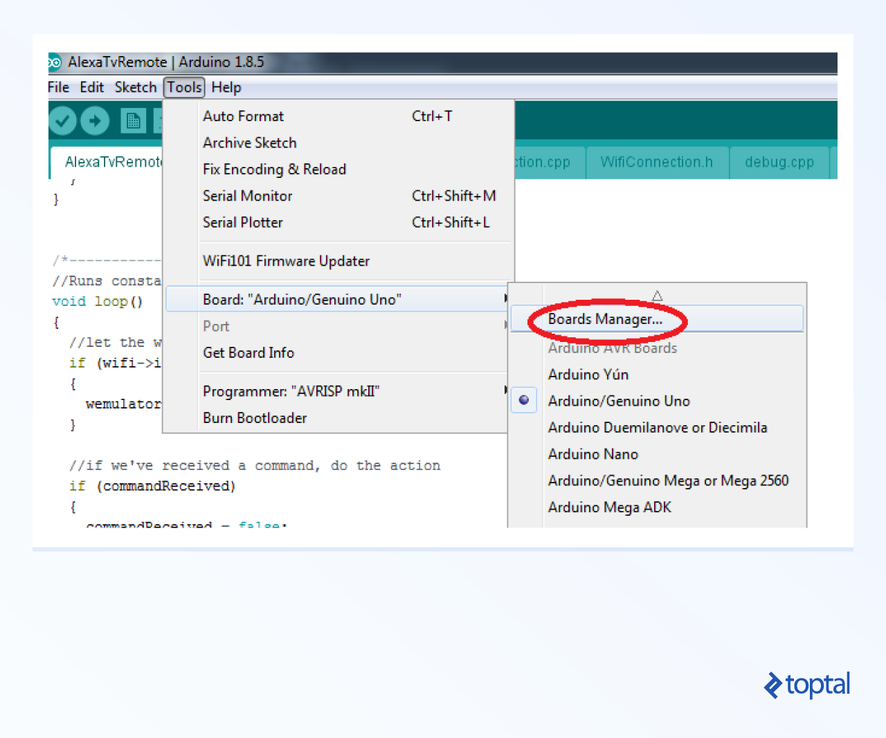
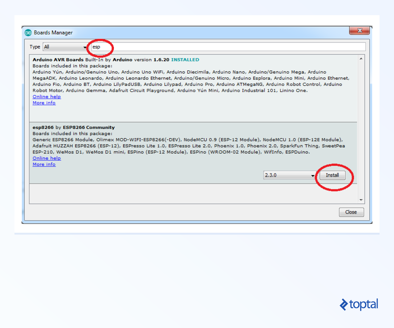
In the filter box, type “ESP8266.”
With the additional boards manager URL added, an entry for “esp8266” should appear. Select it and click “Install.”
- The download may take a while.
- Restart your Arduino IDE.
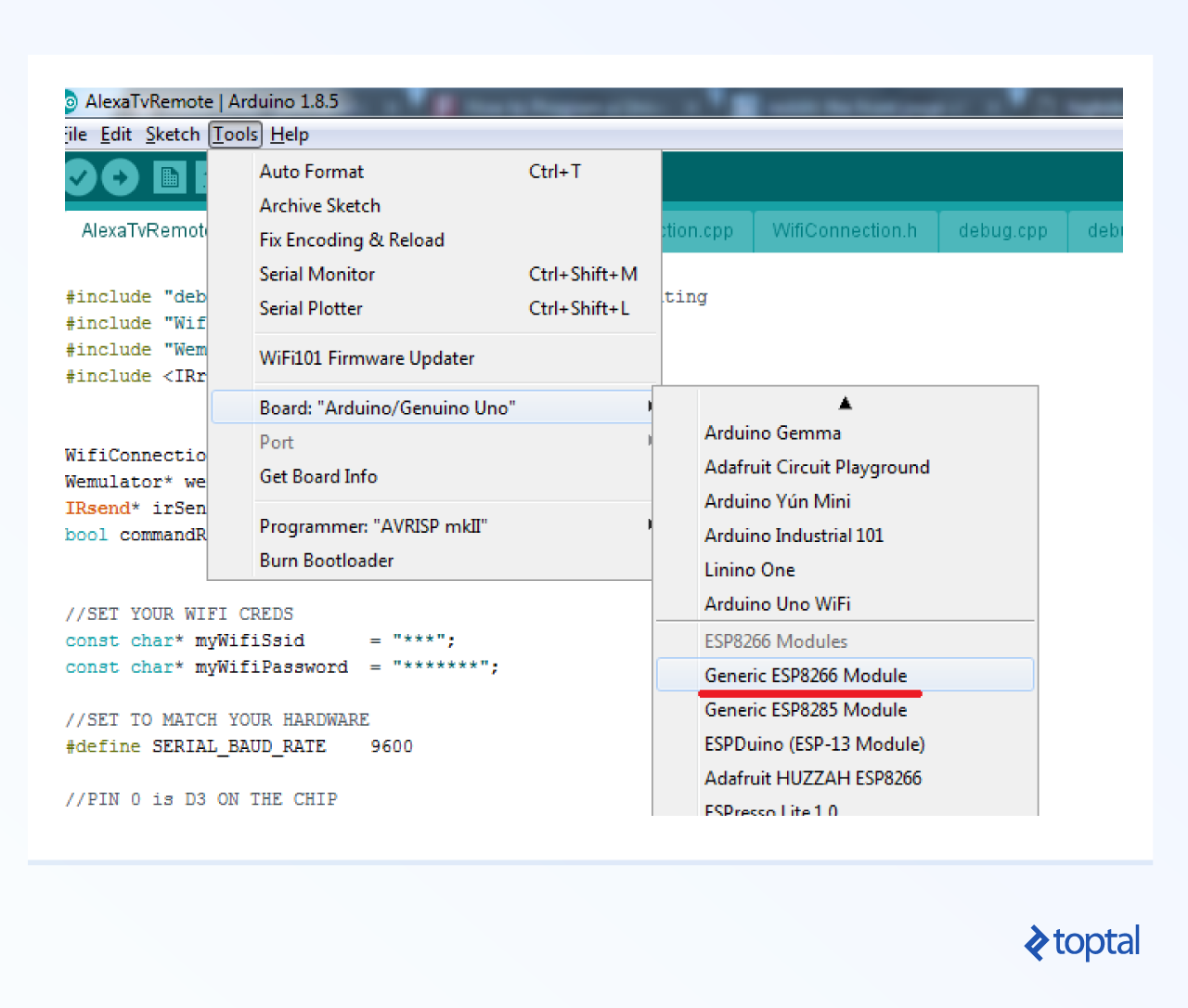
- Go to Tools -> Board: and scroll down to “Generic ESP8266 Module” and select it.
Incorporating External Libraries
Arduino provides multiple ways to integrate external libraries, known as “Sketches,” into your projects. For simplicity, we’ll use the most straightforward method in this guide: folder copying. We’ll add two external libraries: IRemoteESP8266 and https://github.com/me-no-dev/ESPAsyncTCP.
- Locate the “libraries” directory in the tutorial code on GitHub.
- Find the main Arduino installation directory (e.g., C:\Program Files\Arduino) and locate the “libraries” subdirectory within it.
- Copy the “IRemoteESP8266” directory from the tutorial’s “libraries” folder into the Arduino “libraries” directory.
- Repeat the process, copying the “ESPAsyncTCP” directory from the tutorial’s “libraries” folder to the Arduino “libraries” directory.
- Restart the Arduino IDE.
You now have the IR transmitting and async TCP libraries included in your project.
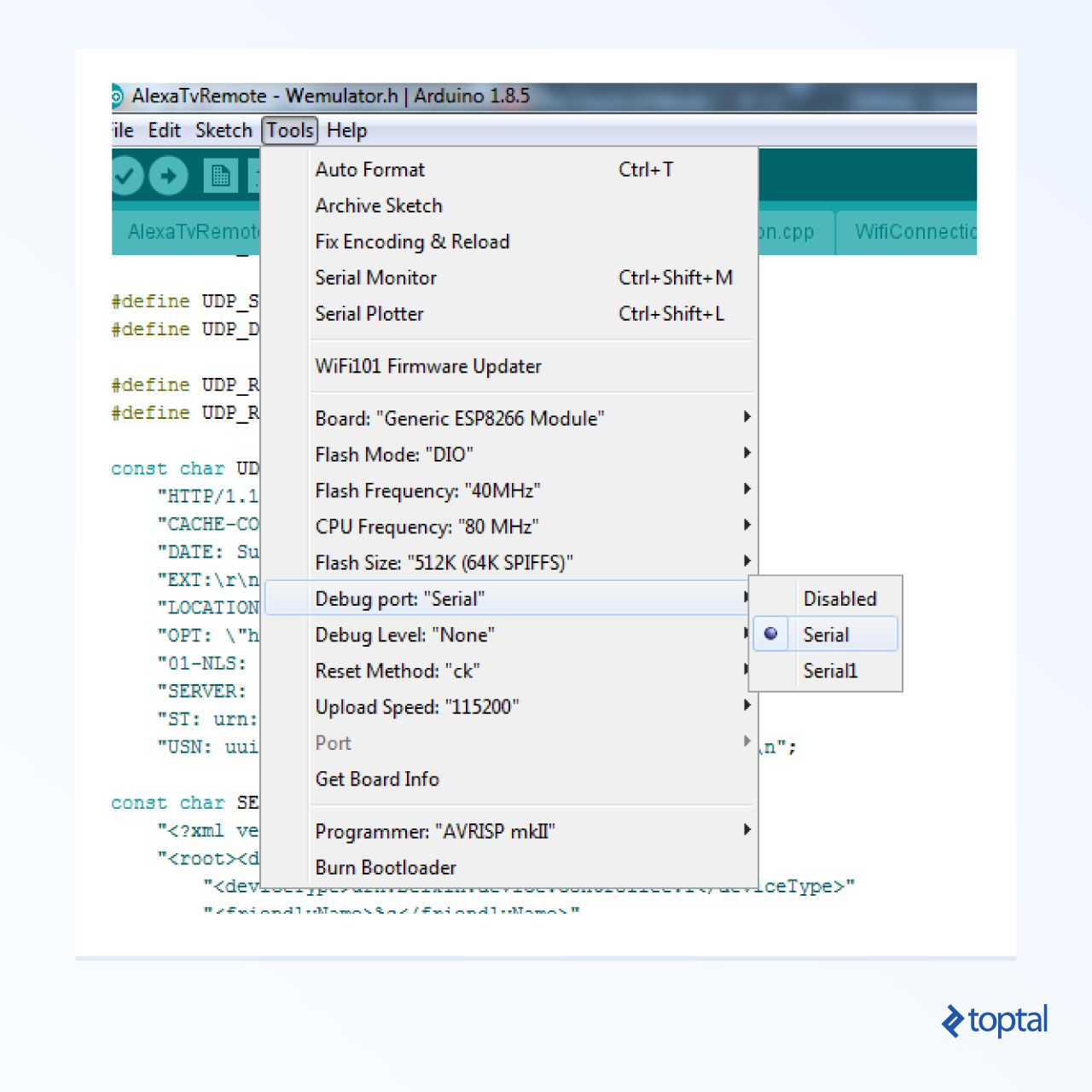
Settings
The provided image illustrates common settings that work with my hardware setup but may vary. You can start with these settings, but be prepared to adjust them based on your specific chip and adapter. Since I’m using nodemcu, I had to switch the reset method from the default “ck” to “nodemcu.” Also, set the “debug port” to “serial” to enable serial debugging. While your setup is likely similar, minor adjustments might be needed to ensure successful compilation and flashing.
ESP8266 Hello World: A Quick Test
Arduino projects begin with a .ino file containing two entry points: setup and loop. In our “hello world,” we’ll briefly illuminate a light on the ESP8266 to confirm that our code functions properly.
| |
Compilation and Flashing Made Easy
With a correctly configured setup, compiling and flashing the code is straightforward. To compile without flashing, simply select Sketch -> Verify/Compile from the Arduino menu.
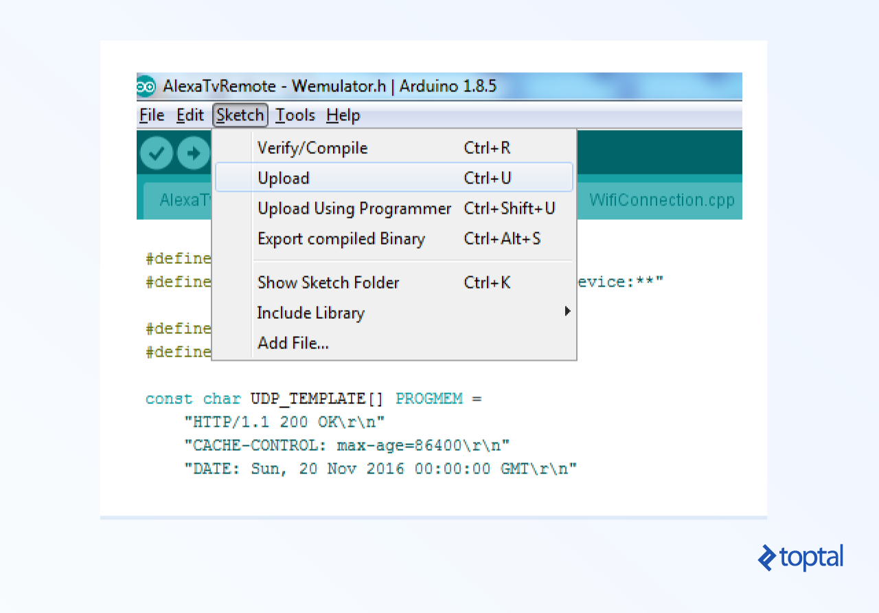
To flash the code to the ESP8266 after compilation, choose Sketch -> Upload from the Arduino menu.
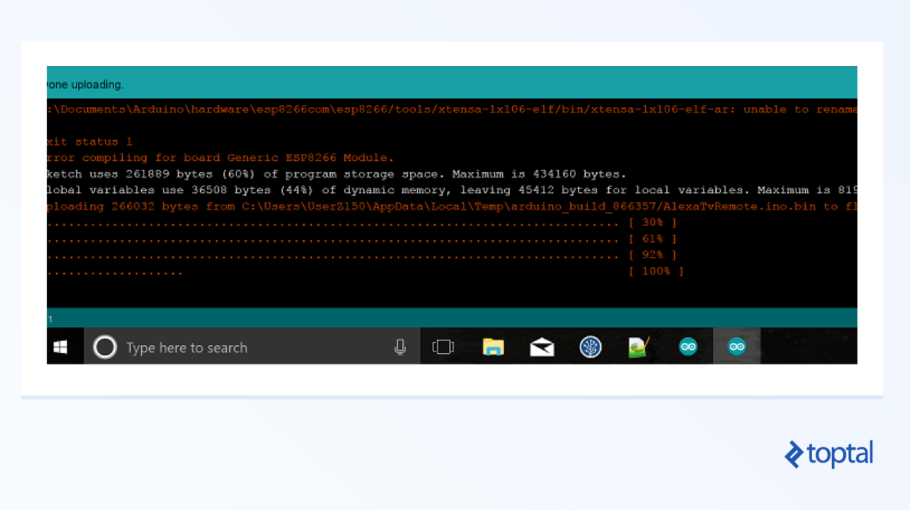
Upon successful flashing, a progress bar will advance from 0% to 100%, during which the LED on your ESP8266 will likely blink or flash.
To test serial debugging:
- Ensure that the debug port is set to Serial (Tools -> Debug port).
- Once the code is flashed, open the Serial Monitor (Tools -> Serial Monitor).

The serial debugger should display the following after a successful startup:
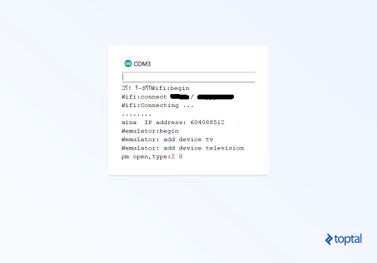
With that confirmed, we’ll verify our IR output. Let’s send a signal through our IR transmitter and verify its transmission.
We’ll use an existing Arduino IR library to assist us. Arduino’s modularity shines here, allowing easy integration of libraries and modules.
Simply follow the instructions in the Git repository’s README file to install it within Arduino.
This code will repeatedly activate the IR transmitter. Although IR is invisible to the naked eye, here’s a tip: with the code running (verified via the debugger), point your mobile device’s camera at the IR diode bulb. A functional setup will show the bulb turning on and off. You can test this with a standard TV remote too. The following code snippet should cause the IR bulb to blink every half second. It actually transmits the LG on/off command, so it might toggle your LG TV nearby.
| |
Diving into the ESP8266 Tutorial
If everything has gone smoothly, we’re ready to tackle the core of our tutorial.
Establishing a Wifi Connection
Our first step is to connect to the local Wifi network. The code snippet below attempts this connection and reports success through the serial debugger. Remember to replace ‘myWifiSsid’ with your network’s username and ‘myWifiPassword’ with the correct password.
| |
Launching the Wemo Server
Connection established? Great! Now for the heart of our project: the Wemo server.
The source files for this guide include my custom Wemo Emulator. While simpler emulators with less code are available online, mine leverages ESPAsyncTCP for enhanced reliability. Feel free to explore, experiment with, or even write your own emulator - it’s all part of the learning process!
Why ESPAsyncTCP? The number of servers (or devices) you can run concurrently on the ESP8266 using this approach is limited before encountering issues. Alexa might struggle to discover devices, commands could be dropped, and performance might degrade. I’ve found that ESPAsyncTCP maximizes this limit.
Without ESPAsyncTCP, unreliability tends to surface around 10-12 devices; with it, this number increases to approximately 16. If you plan to expand this tutorial and push the chip’s boundaries, I recommend using my version. If you prefer a simpler version for learning purposes, search for “wemo emulator Arduino” online for numerous examples.
We now need to install the ESPAsyncTCP library, following the instructions provided on its Git page, just like we did with the IR library.
This library is included in my ESP8266 Arduino example code. Below is the code to establish a Wifi connection, listen for Alexa’s discovery request, and respond with an “I am Wemo” message:
| |
Preliminary Testing
Let’s test our current setup (Wifi and emulator) with Alexa. This assumes your Alexa is set up and connected to your home network.
Testing Device Discovery:
Say, “Alexa, discover devices.”
Alexa will broadcast a UDP request on your Wifi network, searching for Wemos and other compatible devices. This request should reach the wemulator->listen(); call within the loop() function, which then routes it to the handleUDPPacket(*) method of the Wemulator. The response is dispatched by the nextUDPResponse() method. Notice the content of this response:
| |
This code informs Alexa that it’s dealing with a Wemo device ready to receive commands. Upon receiving this response, Alexa registers the device and remembers to route future smart-home commands to it.
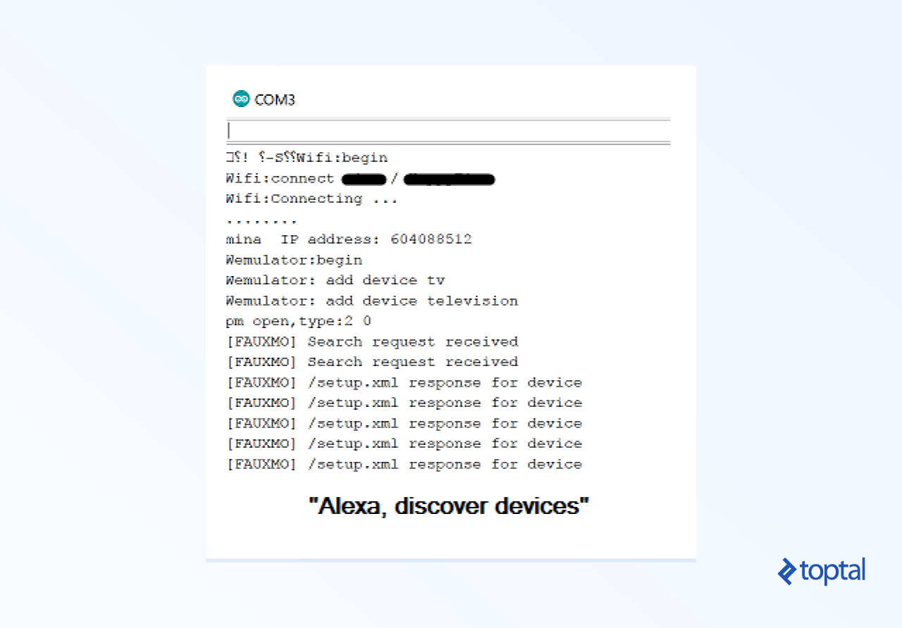
The serial debugger output should resemble the image below. Once discovery is complete, Alexa will verbally confirm the number of devices found on your network.
Within the setup() function, observe the following snippet:
| |
This callback function captures commands from Alexa, with its body defined in WemoCallbackHandler.h (WemoCallbackHandler::handleCallback). Once we capture a command, we can manipulate it as needed. The preceding lines define potential commands using the following code:
| |
These lines establish four distinct “servers” or listeners on the chip, enabling us to use any of the following commands with Alexa:
Alexa, turn on tv Alexa, turn off tv Alexa, turn on television Alexa, turn off television Alexa, turn on my tv Alexa, turn off my tv Alexa, turn on my television Alexa, turn off my television
Issuing any of these commands should trigger our code and execute the callback function, where we can process the command.
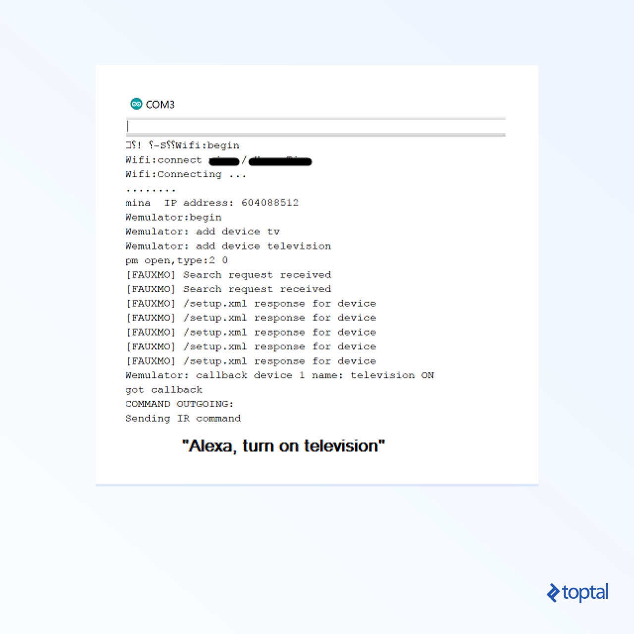
Integrating the IR Command
Now that we’re receiving the command, let’s use it to control our TV. This section combines everything: Wifi, the Wemo emulator, and IR functionality. Since I own an LG TV, I incorporated its specific on/off sequence, sent through the IR library’s sendNEC function (LG uses the NEC protocol).
IR encoding/decoding is a topic in itself, involving message encoding within signal modulation. Each manufacturer often employs its proprietary protocol with varying timings for commands. If you’re interested, explore the IR library’s source code or research online. Fortunately, our IR library handles these details.
For TVs other than LG, a quick Google search will yield the correct code. Here’s the command for Sony TVs (untested):
| |
If you want a truly hands-on approach, set up an IR receiver, point your remote at it, and decode the transmitted codes. However, that’s a topic for another tutorial.
End-to-End Testing
- Position your Alexa device within earshot.
- Place your ESP8266 with the attached IR diode within remote control range of your TV.
- Initiate device discovery by saying, “Alexa, discover devices.” Wait for confirmation (at least one device should be detected).
- Issue a command like “Alexa, turn on my TV” or “Alexa, turn off my TV.”
Alexa should interpret your command as a smart-home request, locate your ESP8266, and transmit the command. Your device, in turn, should receive the command and relay the appropriate IR code to the TV. You can visually confirm IR emission by observing the diode through your phone’s camera.
Because the IR on/off code is the same, the command will toggle the TV’s state. If the TV is off, it should turn on, and vice versa.
Troubleshooting
Wifi Connection Issues
- Did you accurately input your Wifi username and password in the designated variables?
| |
- Are there any error messages or failures reported by the serial debug port during the Wifi connection attempt?
- Is your Wifi network active and accessible from other devices?
Device Discovery Problems
- Saying “Alexa, discover devices” prompts Alexa to search for new devices.
- Ensure your Alexa is configured correctly and connected to the same Wifi network as your ESP8266.
- Examine the
Fauxmo::handle()function in Fauxmo.h. This code executes when the ESP8266 receives the discovery request. Insert debug messages to check if the code following
| |
is being executed. If not, the command is not being received. If it is, the command is received but might not be handled correctly. Trace the code from there to pinpoint the issue.
- An excessive number of discoverable devices on your network can slow down or even hinder the discovery process.
Command Reception Issues
- Issuing the command “Alexa, turn my TV on” should trigger your
WemoCallbackHandler::handleCallbackhandler (located in WemoCallbackHandler.h). If not, add debug messages to ensure this handler is invoked. Also, make sure Alexa recognizes your device by saying “Alexa, discover devices” beforehand. This assumes device discovery was successful.
IR Diode Functionality
- As mentioned earlier, use your phone’s camera to check for IR emissions from the diode when you expect it to transmit. If functional, you should see the light flickering.
Reversed IR Signal
Incorrect wiring of your IR diode can invert the signal. Without delving too deep into electronics, improper wiring can cause the IR light to be ON by default and turn OFF when the IRSend library attempts to activate it. In this scenario, the IR light (visible through the camera) would remain on continuously after the
setup()code executes. Commenting out all code withinloop()should demonstrate this continuous ON state.To rectify this, navigate to the libraries/IRemoteESP8266/src folder within the tutorial code and locate the constructor:
| |
The "inverted" argument and its handling logic are relevant here. If your wiring is indeed inverted, instead of rewiring (although possible), a minor code modification can address this. Change this line in AlexaTvRemote.ino:
| |
to
| |
Correctness of IR Code and Command
If all else fails and your TV remains unresponsive, the IR code is likely the culprit. Try various function calls from the IR library (e.g.,
sendLG,sendPanasonic,sendSharp, etc.), ensuring the one used matches your TV model. While unlikely, it’s possible your TV model isn’t supported by the library.Verify that you are using the correct code for your device. Online research can help determine the right code. As a last resort, you can capture the code emitted by your TV remote’s Power button, though this requires a different tutorial and additional hardware.
Conclusion
Congratulations! You’ve successfully (hopefully) completed this multi-faceted tutorial, covering:
- Alexa interaction
- Embedded programming basics
- Working with the ESP8266 chip
- Utilizing the Arduino IDE
And, of course, you’ve gained the convenience of voice-controlled TV operation.
Hack vs. Official API
Why is this a workaround and not part of Alexa’s official API? It would be beneficial if Amazon provided a comprehensive API for direct communication between Alexa devices and other network devices without relying on the “skill” or “smart-home” paradigms, which necessitate routing everything through AWS. Unfortunately, such an API is currently unavailable.
Further Exploration
- Expand your project to include a wider range of remote control commands, allowing you to control channels, volume, and other TV functions.
- Push the ESP8266’s limits by experimenting with the number of commands it can handle simultaneously. Without advanced programming techniques, this number is limited to roughly a dozen.
- For hardware enthusiasts, explore controlling devices directly connected to ESP8266 chips instead of using IR, such as lighting systems. The possibilities are endless!