The main board and volume control board restoration is finished.
Despite the Beomaster 1900 and 2400 receivers having a small footprint, their restoration is deceptively complex. Replacing the numerous capacitors always serves as a reminder of the intricate internal workings.
Upon arrival, the main board appeared as shown:

After replacing the electrolytic and tantalum capacitors, the main board looked like this:

Here’s a closer look:
Following my usual practice, I replaced electrolytic and tantalum capacitors with values of 4.7uF and below with red rectangular WIMA MKS capacitors. These are non-polarized, offering a suitable replacement.
For capacitors exceeding 4.7uF, I used high-quality capacitors rated at 105°C. Matching the voltage rating of the original capacitors was prioritized throughout.

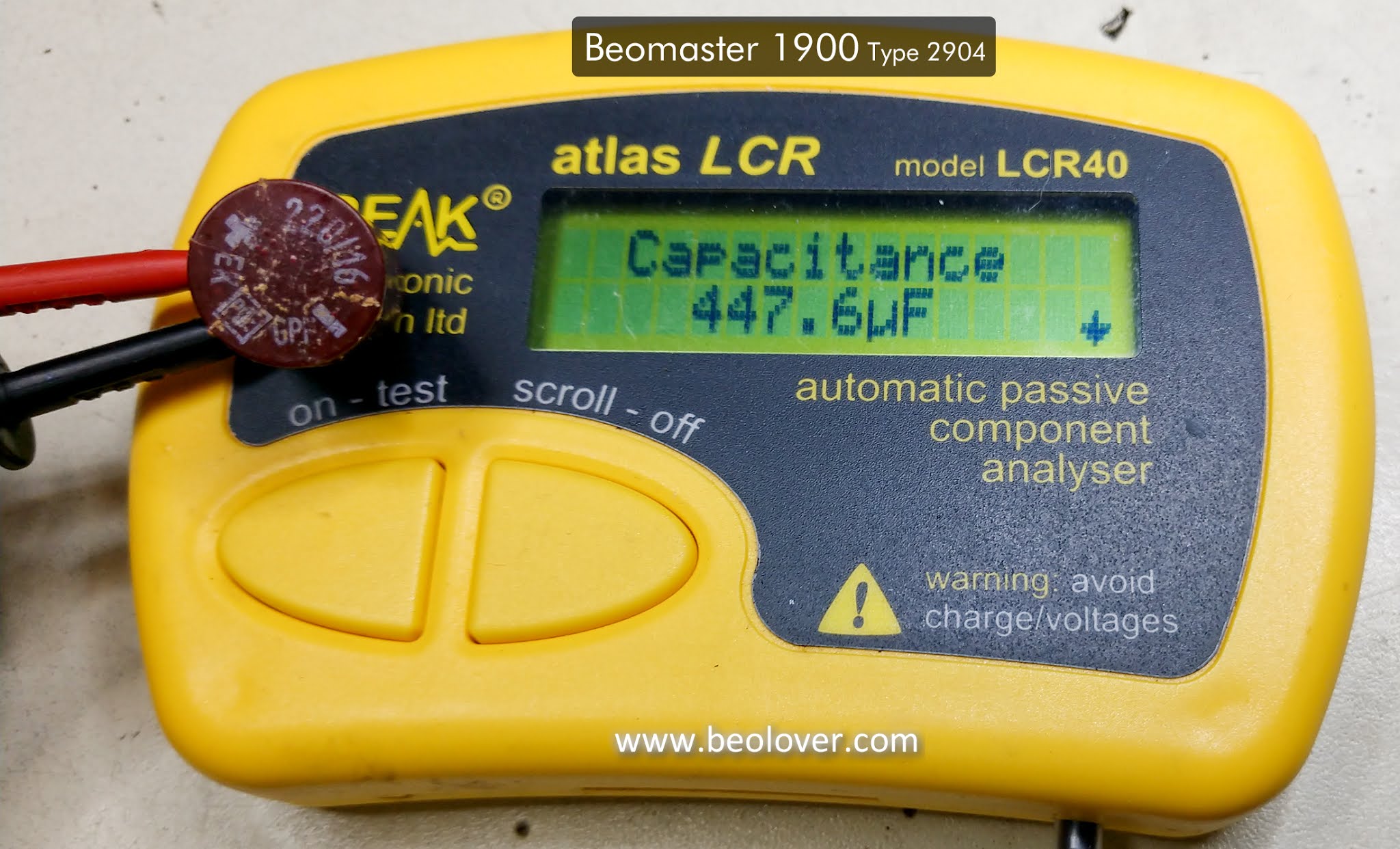
As observed in previous Beomaster 1900/2400 restorations, a significant number of capacitors showed tolerance deviations ranging from 30% to over 100%.
I meticulously measured each removed capacitor. While not all measurements are pictured, these examples highlight the common findings.
An original 220uF capacitor, now significantly out of tolerance:
A 2.2uF capacitor exhibiting a similar issue:

Replacing these significantly deviated capacitors with new ones will greatly improve performance.
A new Nichicon 220uF capacitor:

A single 10uF tantalum capacitor within the FM tuner was the only one not replaced. Its measured value matched its rating, making replacement unnecessary.
As documented earlier, this Beomaster 1900 had a history of problems with the +15 VDC power supply’s rectifier bridge.

The makeshift rectifier bridge was replaced with a single unit. Additionally, the previously replaced capacitors, while still functional, were also replaced to ensure all electrolytic capacitors were new.

Typically, the two large reservoir capacitors for the output amplifier voltage rails remain within tolerance. This Beomaster was no exception; however, I opted to replace them due to the involved process. This proactive approach prevents revisiting this task later.
The existing reservoir capacitors:

And the replacements:

During the main board restoration, I noticed the +15 VDC regulator’s mounting appeared less than ideal. The dried-out thermal paste necessitated a more robust solution.
To address this, the old paste was removed, and the regulator was remounted using a SIL-Pad.


This modification, along with the added hot glue for the 2200uF capacitor of the +15 VDC supply, ensures better stability and heat dissipation.
The left and right channel 250Ω trimmers on the main board, responsible for the output amplifiers’ no-load current adjustment, were replaced with new, sealed, multi-turn versions.

With the main board complete, attention shifted to the Volume Control Board.
The board before any work:

And after capacitor replacement:

The reinstalled Volume Control Board:

This phase involved replacing sixty-four capacitors, two trimmers, and the four diodes of the bridge rectifier.
Removed components:

The second Beomaster 1900 receiver will undergo the same process.
Upcoming tasks include recapping the Tone Control/FM Tuner board and replacing the Beomaster 1900 indicator lamps. Once these are finalized, the enjoyable part begins: testing.